
Product Manual

8
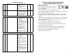
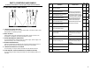
PART 3: CONTROLS AND PANELS
An overview of the MUTT
®
’s controls, inputs, outputs and their functions.
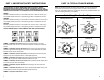
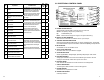
3.1 LEFT AND RIGHT SIDE PANELS
A. 7 ROUND PIN CABLE TEST INPUT
For testing the integrity of a 7 round pin trailer cable. Can also be used to verify
that the MUTT
®
is operating correctly.
B. SHOP AIR INPUT
A bulk head air input with external stone fi lter that is used to connect an air
compressor to the MUTT
®
for testing air brakes on a trailer.
C. 20 AMP INDEPENDENT POWER INPUT
For connecting external 12DC 20 amp max. power supply. (Power supply is an
optional accessory, not for battery charging.)
D. CHASSIS GROUND OUTLET
Insert the supplied ground cable into this socket for trailers using the frame or
body for ground connection instead of the ground pin in the harness.
E. 7 ROUND PIN CABLE OUT TO TRAILER
For connecting 7 round pin trailer to the MUTT
®
to test electrical circuits.
F. 12V DC BATTERY TRICKLE CHARGE INPUT (CIGARETTE SOCKET)
For connecting the trickle charger to the MUTT
®
’s internal battery (battery not
included).
Left Side Right Side
C D E
F
A
B
33
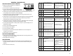
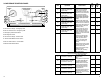
Fault
Code
Explanation Possible Causes
PLC
Select
1M
PLC
Select
2M
80
Output leakage or poor insulation on any
of the valve channels.
Modulator valve solenoid failure or
valve cable damage. Indicates that
the solenoid or its cable has a short
circuit to positive power (12 volts DC).
The most likely cause is a damaged
cable or solenoid. Disconnect the
indicated solenoid and check the
resistance at the solenoid pins.
If solenoid checks good and 80-89
code still exists, check ECU.
XX
81
Hold solenoid short circuit to Permanent
Power on Red valve channel.
X
82
Hold solenoid short circuit to Permanent
Power on Blue valve channel.
X
83
Hold solenoid short circuit to Permanent
Power on Yellow valve channel.
X
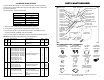
87
Dump solenoid out shorted to Permanent
Power on Red valve channel.
X
88
Dump solenoid out shorted to Permanent
Power on Blue valve Channel. X
89
Dump solenoid out shorted to Permanent
Power on Yellow valve channel. X
90
Low supply voltage fault. This code is not
stored in memory.
Verify 12 V DC power source. Do Not
Use Battery Charger as Power Supply.
ECU minimum operating voltage is
8.5 V DC.
XX
91
No internal ABS ECU solenoid voltage
available.
Verify permanent power is present.
XX
92 Power input over voltage fault.
Verify 12 VDC power source. Do Not
Use Battery Charger as Power Supply.
ECU maximum operating voltage is
16.0 VDC.
XX
93 Short circuit on ABS ECU internal relay.
Replace ECU
XX
99 ABS Corrupt Memory X X
9A ABS Corrupt Memory X