
Product Manual


24
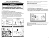
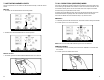
8.3 LEAK DOWN TESTING
You must always test the Emergency Side before testing the Service Side. Trying to
test the Service Side fi rst will result in erroneous readings.
EMERGENCY SIDE LEAK DOWN TESTING
1. After setting the desired working pressure, set the Emergency Side Air Ball Valve to
the CLOSED position. This will begin the leak down test.
2. Observe the needle on the air gauge and note any PSI drop after pressure stabilizes.
3. Look for air loss according to your local specifi cations by noting consistent air
drop over time. If air pressure continues to drop at an unacceptable rate, you can
turn your air supply back on by setting the Emergency Side Air Ball Valve to OPEN
and attempt to fi nd the source of the leak in the air system.
SERVICE SIDE LEAK DOWN TESTING
1. Set the Emergency Side and Service Side Air Ball Valves to the OPEN position.
Set the Service Side Brake Control Switch to the PRESSURIZE position. (This fi lls
the Service Side air lines.)
2. Once the Service Side is fully charged, set the Service Side Air Ball Valve to the CLOSED
position.
3. Observe the needle on the air gauge and note any PSI drop after pressure stabilizes.
4. Look for air loss according to your local specifi cations by noting consistent air
drop over time. If air pressure continues to drop at an unacceptable rate, you can
turn your air supply back on by setting the Service Side Air Ball Valve to OPEN
and attempt to fi nd the source of the leak in the air system.
Set Emergency Side Air Ball Valve to CLOSED
Set Service Side Air Ball Valve to CLOSED
17
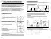
7.2 GROUND INTEGRITY TEST
Each time the MUTT
®
is powered on, it automatically runs a Ground Integrity Test. A good
ground connection must be established for the MUTT
®
to operate a trailer’s electrical system.
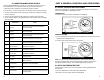
1. Immediately after power up, the green lights around the control knob will illuminate.
2. A solid/healthy ground connection is indicated by a steadily illuminated Ground
Integrity Indicator.
3. Bad/poor ground or bad cable condition is indicated by all of the LED’s blinking
simultaneously. See ESTABLISHING A CHASSIS GROUND below.
4. When one or more green circuit LEDs blink while the Ground Integrity Indicator
is steadily illuminated indicates that a solid ground has been established, but an
open circuit has been detected. Refer to OPEN CIRCUIT on pg. 18.
CHASSIS AND PIN GROUNDS
A poor ground warning may be an indication that the connected trailer is only wired
for chassis ground. There are two ground types. 1) Pin Ground: The ground wire
from each light assembly is wired through the main harness up into the trailer plug.
2) Chassis Ground: The ground wire from each light assembly is grounded directly to
the trailer chassis. Ground with the truck is established at the king pin.
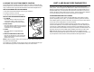
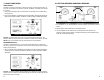
ESTABLISHING A CHASSIS GROUND
1. To simulate the king pin on a chassis ground
connection and bypass the ground integrity fault,
plug the supplied 10 ft. chassis ground cable into
the MUTT
®
’s Chassis Ground Outlet.
2. Using the alligator clip, attach the other end of the
chassis ground cable to the chassis of the trailer.
3. Be sure that you are attaching to a clean, dry metal for an effective ground.
GOOD GROUND BAD/POOR GROUND
DO NOT
Assume that a Bad
Ground Warning is a
Result of a Faulty Trailer.
Check Cable Connection.
Put the Chassis Ground Cable into the Outlet