
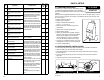
Product Manual


12
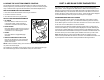
PART 5: PRETESTING CHECKLIST
The pretesting checklist should always be completed prior to using the MUTT
®
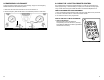
UNIT PLACEMENT
• Place the tester on a fl at, level surface.
• Chock trailer wheels to avoid rolling before testing brakes.
MAINTAIN CONNECTORS
Dielectric grease should be used on all connections to avoid corrosion. If a bad
connection exists at the terminal junction, you may get an erroneous reading and
the MUTT
®
will not work properly.
• Make sure you have a solid connection in the socket.
• Be certain the 7 pins in each plug are clean and spread to the proper size.
• Always check the MUTT
®
connector pins at the side of the MUTT
®
for proper
expansion. Over time, the pins may bend in slightly resulting in a poor connection
between the connector and the cable ends. A fl at head screwdriver can be used
to expand the pins until a tight connection is made.
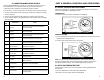
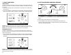
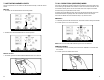
CABLE TESTING PROCEDURE
The MUTT
®
has a special cable feature to test 7-way round pin cables for continuity.
The cable testing feature can be used to test a tractor’s cable, or the supplied MUTT
®
cable. All cables should be tested prior to MUTT
®
operation.
• Insert each end of the cable into both side connectors on the MUTT
®
. Be sure to
push the cable ends in fi rmly until they reach the bottom of the connector.
• Turn main power switch to a desired power supply.
• Once the power is selected, the green lights around the control knob will blink
and disappear one at a time until only the Ground Integrity Indicator remains solid
green. Once the initial check has been performed, poor cable conditions will be
shown by a blinking light for the problem circuit.
• If the cable has an open circuit or continuity problem, the corresponding circuit will
fl ash repeatedly.
• Further testing can be performed by selecting each circuit individually via the
control knob or remote. When an open circuit is detected, the LED for the circuit
will fl ash and an audible alert will be heard.
29
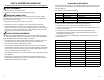
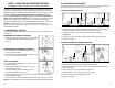
9.2 HALDEX BLINK CODES
To access Haldex Blink Codes, you must select the Brake Light Circuit and press the
control knob to cycle the Auxiliary Circuit the appropriate number of times using the
following directions:
See table below for modes and sequences:
1. Make sure trailer is stationary and wheels are properly chocked.
2. On the MUTT
®
, turn the control knob to select Brake Light Circuit.
3. Push the control knob to cycle Auxiliary Circuit ON for each desired ignition cycle.
Auxiliary Circuit will fl ash.
5. Each Ignition Cycle must end with both Brake Light and Auxiliary Circuits
simultaneously powered. To do this, press and hold the control knob for fi ve
seconds during the last ON cycle.
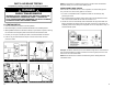
6. Count number of blinks on trailer ABS lamp, see following charts (pg. 28-32) for
specifi c fault info.
Mode Description Ignition Cycles (Hold 1 Second ON/OFF)
1 Simple/Wheel Speed Mode ON, off, ON
2 Active Faults Mode ON, off, ON, off, ON
3 Stored Faults/Clear Mode ON, off, ON, off, ON, off, ON
4 Confi guration Mode ON, off, ON, off, ON, off, ON, off, ON
Item Flash Count Actual Fault
System OK Light Stays On 07
Sensor 1A 1 Flash 01
Sensor 1B 2 Flashes 02
Sensor 2A 3 Flashes 03
Sensor 2B 4 Flashes 04
Sensor 3A 5 Flashes 05
Sensor 3B 6 Flashes 06
Red Valve 7 Flashes 61, 67, 71, 77, 81, & 87
Blue Valve 8 Flashes 62, 68, 72, 78, 82, & 88
Yellow Valve 9 Flashes 63, 69, 73, 79, 83, & 89
Low Voltage 10 Flashes 90
ECU Failure 11 Flashes 93, 99, & E-Codes