
Product Manual
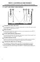
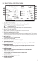
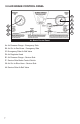

3.2 ELECTRICAL CONTROL PANEL
A. POWER SOURCE SWITCH
Select between Internal Battery, External Power or Power Off.
Center: OFF (battery charge in this position only)
Up: Installed Battery ON
Down: External Power ON (power supply is an optional accessory)
B. BACKLIT 30 AMP AMMETER
Meter shows current draw of a selected circuit up to 30 amps.
C. TROUBLE WARNING INDICATORS
Flashing red LEDs indicate problems that may exist in a selected circuit. This includes
the Overload Indicator, Open Circuit Indicator, and Reversed (Battery) Polarity Indicator.
D. MUTE SWITCH
ON disables sound. OFF enables sound.
E. AUTO CYCLE INDICATOR
Illuminates when Auto Cycle Mode is engaged.
F. VOLTAGE INDICATOR
Shows supplied battery voltage integrity. Operating voltage range: 12/24 volt DC.
G. GROUND INTEGRITY
A large green LED above the control knob indicates ground status. Ground
integrity is automatically veried when power is turned on.
H. CONTROL KNOB
Knob activates all electrical test modes and circuits to be diagnosed.
I. CIRCUIT INDICATORS
The small green LEDs illuminate or blink in testing phase.
J. HAZARD SWITCH
Activate the four-way ashers on trailer.
K. 30 AMP FUSE SOCKET
Overload protection.
6
A
B
D
Electrical Control Panel
C
F
E
G
H
I
J
K