
Product Manual
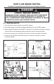
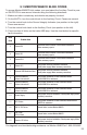
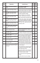

Fault
Code
Explanation Possible Causes
PLC
Select
1M
PLC
Select
2M
00
System OK (with vehicle traveling >
6 mph).
ABS is operational Displays “00”
when traveling > 6 MPH.
X X
01
Red channel wheel speed sensor
wiring S1A has an Open or Short
circuit.
Indicates a wheel speed sensor or its
wiring has short or open circuit. Discon-
nect the relevant sensor and measure
the resistance between the two pins in
the sensor connector housing.
If sensor extensions are used verify
extension continuity and connections.
Replace sensor and/or extension cable.
The Ohm meter reading for the sensor
or sensor and extension cable should be
between 980 and 2350 Ohm (.98K and
2.35K Ohm) If not, replace sensor and/
or extension cable.
X
02
Red channel wheel speed sensor
wiring S1B has an Open or Short
circuit.
X
03
Blue channel wheel speed sensor
wiring S2A has an Open or Short
circuit.
X
04
Yellow channel wheel speed sensor
wiring S2B has an Open or Short
circuit.
X
05
Blue channel wheel speed sensor
wiring S3A has an Open or Short
circuit.
X
06
Yellow channel wheel speed sensor
wiring S3B has an Open or Short
circuit.
X
07 System OK (No Active Fault).
ABS ECU is fully operational. Displays “07”
vehicle is stationary.
X X
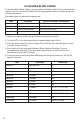
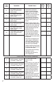
11
Red channel speed sensor S1A has
low sensor output.
Sensor or spring clip is worn or not prop-
erly adjusted, wiring open or short circuit,
wheel bearing not properly adjusted (these
faults will only occur at speeds of greater
than 6 mph). Measure the AC voltage at
the sensor in question while rotating the
wheel at a rate of about one revolution
every two seconds. The output should be
at least 200 millivolts (0.2V AC). If this is
not the case, push in the sensor until it
touches the exciter and rotate the wheel
again. If this doesn’t correct the problem,
then the sensor and the sensor block clip
should be replaced.
If sensor extensions are used verify exten-
sion continuity and connections. Replace
sensor and/or sensor cable.
Inspect exciter teeth for minor damage or
teeth lled with debris. Verify all exciters
have the same number of teeth.
Verify sensor and valve wiring/plumbing
is correct.
See side by side axle by axle congura-
tions.
X
12
Red channel speed sensor S1B has
low sensor output.
X
13
Blue channel speed sensor S2A has
low sensor output.
X
14
Yellow channel speed sensor S2B
has low sensor output.
X
15
Blue channel speed sensor S3A has
low sensor output.
X
16 Yellow channel speed sensor S3B
gap too large. Gap should be kept to
a minimum.
X
26