
Product Manual

13
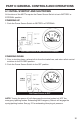
7.2 GROUND INTEGRITY TEST
Each time the MUTT® is powered on, it automatically runs a Ground Integrity Test. A good
ground connection must be established for the MUTT® to operate a trailer’s electrical
system.
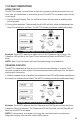
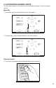
1. Immediately after power up, the green lights around the control knob will illuminate.
2. A solid/healthy ground connection is indicated by a steadily illuminated Ground
Integrity Indicator.
3. Bad/poor ground or bad cable condition is indicated by all of the LED’s blinking
simultaneously. See ESTABLISHING A CHASSIS GROUND below.
4. When one or more green circuit LEDs blink while the Ground Integrity Indicator
is steadily illuminated indicates that a solid ground has been established, but an
open circuit has been detected. Refer to OPEN CIRCUITS on pg. 16.
CHASSIS AND PIN GROUNDS
A poor ground warning may be an indication that the connected trailer is only wired
for chassis ground. There are two ground types. 1.) Pin Ground: The ground wire
from each light assembly is wired through the main harness up into the trailer plug.
2.) Chassis Ground: The ground wire from each light assembly is grounded directly
to the trailer chassis. Ground with the truck is established at the king pin.
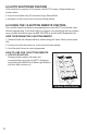
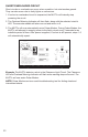
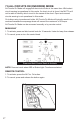
ESTABLISHING A CHASSIS GROUND
1. To simulate the king pin on a chassis ground
connection and bypass the ground integrity fault,
plug a chassis ground cable into the MUTT®’s
Chassis Ground Outlet.
2. Attach the other end of the chassis ground cable
to the chassis of the trailer.
3. Be sure that you are attaching to a clean, dry metal for an effective ground.
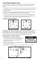
GOOD GROUND BAD/POOR GROUND
DO NOT
Assume that a Bad
Ground Warning is a
Result of a Faulty Trailer.
Check Cable Connection.
Put the Chassis Ground Cable into the Outlet