
Product Manual

7
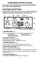
F. TROUBLE WARNING INDICATORS (Fig. 2)
Flashing red LEDs indicate problems that may exist in a selected circuit.
• Overload Indicator • Open Circuit Indicator
• Reversed Battery • Polarity Indicator
• Low Battery • Crossed Circuits
G. BACKLIT 30 AMP AMMETER (Fig. 2)
Meter shows current draw of a selected circuit up to 30 AMPS.
H. POWER SWITCH (Fig. 2)
Select between internal battery, external house current, or power off.
Center: OFF (battery charge in this position only).
Left: internal battery ON.
Right : external power on ON (power supply is an optional accessory).
I. ANTENNA (Fig. 5 & Fig. 2)
Receives RF signal from wireless remote up to 100 feet.
Binding post allows antenna length insertion for further distances in in-
clement weather. It is recommended the antenna be installed for optimum
performance.
J. 20 AMP INDEPENDENT POWER INPUT SOCKET (Fig. 2)
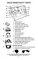
POWER PANEL: (Fig. 3)
Power panel features.
K. 12V DC BATTERY TRICKLE CHARGE INPUT (Fig. 3)
Use for connection of trickle charger to battery. Allows float charge to be
kept on battery when unit is not in use.
L. MUTE SWITCH (Fig. 3)
M. 30 AMP FUSE SOCKET (Fig. 3)
Overload protection.
N. CHASSIS GROUND OUTLET (Fig. 3)
Insert supplied ground cable into this socket for trailers using the frame or
body for ground connection instead of ground pin in harness.
Fig. 3 – Power Panel
NL MK