#9007A SMART MUTT® (7 Round Pin) Mobile Universal Trailer Tester OPERATOR’S MANUAL MADE IN USA A Portable Unit for Commercial Trailer Lighting and ABS Innovative Products of America® Incorporated 888-786-7899 • 234 Tinker Street, Woodstock, NY 12498 • www.ipatools.
(OEM) Original Equipment Manufacturer USA LETTER FROM THE PRESIDENT OF IPA ® My name is Ian Vinci and I would like to thank you for your interest in our products. In today’s world, we have all experienced the lack of service and consideration demonstrated by many companies after you buy their products. They say whatever they can to make the sale, and then it’s like pulling teeth to get any service response out of them.
TABLE OF CONTENTS PART 1: IMPORTANT SAFETY INSTRUCTIONS 4 PART 2: WHAT’S INCLUDED 7 PART 3: CONTROLS AND PANELS 3.1 Left and Right Side Panels 3.2 Electrical Control Panel 8 8 9 PART 4: SETUP 10 Battery Requirements/Installation 10 PART 5: PRETESTING CHECKLIST 11 Cable Testing Procedure 11 PART 6: GENERAL OPERATION 12 12 12 13 13 6.1 Initial Startup and Shutdown 6.2 Auto Shutdown Feature 6.3 Using the 3-Button Remote Control 6.
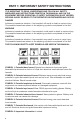
PART 1: IMPORTANT SAFETY INSTRUCTIONS IT IS IMPORTANT TO READ, UNDERSTAND AND FOLLOW ALL SAFETY MESSAGES AND INSTRUCTIONS PRINTED IN THIS MANUAL AND ON THE EQUIPMENT BEFORE OPERATING. IF SAFETY INFORMATION IS NOT HEEDED, SERIOUS INJURY OR DEATH TO THE OPERATOR OR BYSTANDERS MAY OCCUR. DANGER Indicates a hazardous situation, if not avoided, will result in death or serious injury. The possible hazards are shown in the adjoining symbols or explained in the text.
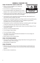
BATTERY GASES, TESTER PREPARATION AND TESTER/CHARGER LOCATION RISK OF EXPLOSION • Gases produced by a battery are highly explosive. • Wear safety goggles and protective clothing, both users and bystanders. • Use in an area having at least four air changes per hour. • Read, understand and follow all instructions for charger, battery, vehicle and any equipment used near battery and charger. • Do not smoke, strike a match, place metal tools on battery or cause a spark in the vicinity of the battery.
GENERAL CHARGER USE RISK OF ELECTRIC SHOCK AND FIRE • Before connecting charger to unit, make sure controls are set to OFF. • Do not remove or bypass the grounding pin. • Do not operate charger with damaged cord or plug. Replace cord or plug immediately if damage occurs. DO NOT Plug Directly Into AC Wall Outlet • Position power cord and charger cables away from the hood, doors and hot or moving engine parts where they could be damaged.
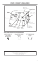
PART 2: WHAT’S INCLUDED Electrical Testing Panel Power Switch Control Knob 7-Round Pin Cable Output MADE IN USA Ammeter Chassis Ground Input Warning Indicators Mute Switch Hazard Switch Fuse Switch 12V Battery Charge Input INCLUDED PARTS AND ACCESSORIES: REMOTE CONTROL FOB (Qty. 1 Included) #MUT-RM3-9007A 500mA BATTERY CHARGER #CHR0001 5 FT.
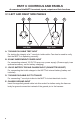
PART 3: CONTROLS AND PANELS An overview of the MUTT®’s controls, inputs, outputs and their functions. 3.1 LEFT AND RIGHT SIDE PANELS A B Left Side C D E Right Side A. 7 ROUND PIN CABLE TEST INPUT For testing the integrity of a 7 round pin trailer cable. Can also be used to verify that the MUTT® is operating correctly. B. 20 AMP INDEPENDENT POWER INPUT For connecting external 12V DC 20 amp max. power supply. (Power supply is an optional accessory, not for battery charging.) C.
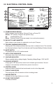
3.2 ELECTRICAL CONTROL PANEL E A F B G C H D I J K Electrical Control Panel A. POWER SOURCE SWITCH Select between Internal Battery, External Power or Power Off. Center: OFF (battery charge in this position only) Up: Installed Battery ON Down: External Power ON (power supply is an optional accessory) B. BACKLIT 30 AMP AMMETER Meter shows current draw of a selected circuit up to 30 amps. C. TROUBLE WARNING INDICATORS Flashing red LEDs indicate problems that may exist in a selected circuit.
PART 4: SETUP BATTERY REQUIREMENTS/INSTALLATION CHOOSING A BATTERY (Manufacturer’s Suggested Replacement: YUASA #YTX14 or Group 14 Equivalent) • Battery Voltage: 12/24V DC • Battery Type: Lead-Acid • Battery Compartment Dimensions: 5 7/8" L x 5 3/4" H x 3 3/8" W • Battery Protection: In-line 30 amp Fuse for Overcharge INSTALLING AN INTERNAL BATTERY 1. Remove the four 8/32" x 1/4" Phillips head screws in the back of the MUTT®. DO NOT Use 24 Volts on a Trailer Wired for 12 Volts! 2.
PART 5: PRETESTING CHECKLIST The pretesting checklist should always be completed prior to using the MUTT UNIT PLACEMENT • Place the tester on a flat, level surface. • Chock trailer wheels to avoid rolling. MAINTAIN CONNECTORS Dielectric grease should be used on all connections to avoid corrosion. If a bad connection exists at the terminal junction, you may get an erroneous reading and the MUTT® will not work properly. • Make sure you have a solid connection in the socket.
PART 6: GENERAL CONTROLS AND OPERATIONS 6.1 INITIAL STARTUP AND SHUTDOWN All functions of the MUTT® require the Power Source Switch to be in BATTERY or EXTERNAL position. POWERING UP 1. Push the Power Source Switch to BATTERY or EXTERNAL. 0 20 10 30 DC AMPERES Set Power Source to BATTERY or EXTERNAL POWERING DOWN 1. Push the Power Source Switch to the OFF position. 0 10 20 30 DC AMPERES Set Power Source to OFF 6.
6.3 USING THE 3-BUTTON REMOTE CONTROL The included remote control(s) is preprogrammed to your MUTT® and should never lose its programming. In the event that you suspect your remote has lost its programming, contact technical support at 888-786-7899, or email tech247@ipatools.com. HOW TO PROGRAM THE 3-BUTTON REMOTE 1. Press and hold the On/Off Button while turing on the MUTT®. 2. Continue to hold for 2 seconds. 3. Your Remote Control is now programmed. HOW TO USE THE WIRELESS REMOTE 1 1.
PART 7: ELECTRICAL/LIGHTING TESTING Complete the pretesting checklist prior to all testing procedures. The MUTT® is microprocessor controlled and features a special diagnostic firmware, designed to seamlessly integrate with your preferred methods of testing. The MUTT® will power the selected electrical circuits and instantly alert you to any signs of a faulty condition.
7.2 GROUND INTEGRITY TEST Each time the MUTT® is powered on, it automatically runs a Ground Integrity Test. A good ground connection must be established for the MUTT® to operate a trailer’s electrical system. 1. Immediately after power up, the green lights around the control knob will illuminate. 2. A solid/healthy ground connection is indicated by a steadily illuminated Ground Integrity Indicator. 3. Bad/poor ground or bad cable condition is indicated by all of the LED’s blinking simultaneously.
7.3 FAULT INDICATION OPEN CIRCUIT The MUTT® senses no load which is often the symptom of a disconnected wire, cut wire, poor pin connection or bad return ground. The MUTT® can detect open circuits in two ways. 1. During Ground Integrity Test: An individual circuit will blink and no audible alerts will be present. 2. During circuit selection: The selected circuit’s LED will blink, while simultaneously the Open Circuit Indicator will flash. The MUTT® will also provide an audible alert (beep).
NOTE: In some cases, a crossed circuit may be a normal function of advanced diagnostic testing, such as with certain ABS systems. SHORT/OVERLOADED CIRCUIT Short circuits or overloads can occur when a positive, hot wire touches ground. They can also occur due to faulty lights or connectors. 1. If a short or overloaded circuit is suspected, the MUTT® will instantly stop powering the circuit. 2. The Overload Warning Indicator will then flash, along with the selected circuit’s LED.
7.4 ACTIVATING HAZARD LIGHTS: The four-way flashers on the vehicle can be activated manually or with the remote control. Manually 1. To activate, set the Hazard Switch to the ON position. Set the Hazard Switch to the ON Position 2. To deactivate, set the Hazard Switch to the OFF position. Set the Hazard Switch to the OFF Position Remote Control 1. To activate, press and hold the DOWN ARROW button for 5 seconds.
7.5 ALL CIRCUITS ON (OVERRIDE) MODE: All Circuits On Mode will engage all electrical circuits at the same time. While short circuit sensing is operational in this mode, if a short circuit is found, the MUTT® will not be able to identify which circuit is the cause of the short. Open and crossed circuits sensing is not operational in this mode. On trailers using incandescent bulbs, All Circuits On Mode will typically result in an overload because the amperage draw will exceed the maximum of 20 amps.
PART 8: ABS BLINK CODE DIAGNOSTICS The MUTT® can be used to access ABS Blink Codes on trailers equipped with ABS systems. Trailers equipped with ABS feature an ABS Control Unit (ECU) which detects any electrical fault in the trailer ABS. Most trailers with ABS will also have a dedicated ABS lamp on the driver side. Each fault has a code. When a fault occurs, the ECU stores the code for that fault in its memory.
8.1 MERITOR/WABCO BLINK CODES To access Meritor/WABCO blink codes, you must select the Auxiliary Circuit to power ON/OFF/ON in one second intervals using the following directions: 1. Make sure trailer is stationary and wheels are properly chocked. 2. On the MUTT®, turn the control knob to the Auxiliary Circuit. Pause one second. 4. Turn the control knob to the Ground Integrity Indicator (one position to the right). Pause one second. 5.
8.
Fault Code Explanation 00 System OK (with vehicle traveling > 6 mph). ABS is operational Displays “00” when traveling > 6 MPH. 01 Red channel wheel speed sensor wiring S1A has an Open or Short circuit. 02 Red channel wheel speed sensor wiring S1B has an Open or Short circuit. Indicates a wheel speed sensor or its wiring has short or open circuit. Disconnect the relevant sensor and measure the resistance between the two pins in the sensor connector housing.
Fault Code Explanation 21 Red channel wheel speed sensor S1A has an erratic output voltage. 22 Red channel wheel speed sensor S1B has an erratic output voltage. 23 Blue channel wheel speed sensor S2A has an erratic output voltage. 24 Yellow channel wheel speed sensor S2B has an erratic output voltage. 25 Blue channel wheel speed sensor S3A has an erratic output voltage. 26 Yellow channel wheel speed sensor S3B has an erratic output voltage.
Fault Code 41 42 43 Explanation Possible Causes For a 2M System, verify sensor and valve wiring/plumbing is correct. (See Side-BySide and Axle-By-Axle configurations). Slow brake release, foundation brake Slow wheel recovery on Blue valve mechanical faults, dry bushings, broken channel. ABS valve, restricted piping. Check for Slow wheel recovery on Yellow valve kinks and blockage etc., incorrect airlines, wiring. channel. Slow wheel recovery on Red valve channel.
Fault Code Explanation 80 Output leakage or poor insulation on any of the valve channels. 81 Hold solenoid short circuit to Permanent Power on Red valve channel. 82 Hold solenoid short circuit to Permanent Power on Blue valve channel. 83 Hold solenoid short circuit to Permanent Power on Yellow valve channel. 87 Dump solenoid out shorted to Permanent Power on Red valve channel. 26 88 Dump solenoid out shorted to Permanent Power on Blue valve channel.
8.3 BENDIX BLINK CODES To access Bendix Blink Codes you must select the Auxiliary Circuit and press the control knob to cycle the Brake Light Circuit the appropriate number of times using the following directions: See table below for modes and sequences: Mode Cycle Brake Light Power Display Active DTCs 3 times Display Inactive DTCs 4 times Clear Active DTCs 5 times Display Configuration 6 times Display Odometer Mileage 7 times Reset Configuration 8 times 1.
4 6 SAL Sensor configuration error 5 6 SAR Sensor configuration error 6 1 Over-voltage 6 2 6 3 Verify correct ABS configuration using blink codes or other diagnostic tools. If needed, reset to the default ABS configuration and power-up to initiate auto-configuration. 3 13 4 13 Power supply diagnostic trouble code. 251 3 Low-voltage Power supply diagnostic trouble code. 251 4 Excessive power line resistance Power supply diagnostic trouble code.
ELECTRONIC CONTROL UNIT (ECU) 11 1 ECU internal error Check for damaged or corroded connectors. Check for damaged wiring. After repairs or if no issues found, then clear faults. If faults return, replace the TABS-6 Module. 254 12 11 2 ECU configuration error Verify correct ABS configuration using blink codes, PC-diagnostics or other off-board diagnostic tools. If needed, reset to the default ABS configuration and power-up to initiate auto-configuration.
PART 9: TYPICAL TRAILER WIRING Note: Not all trailers/vehicles are wired to this standard. The use of an electrical circuit tester is necessary to ensure proper match of vehicle’s wiring to trailer’s wiring. On some trailers with 6-way round plugs, the 12V wire and electric brake wire may be reversed (particularly horse trailers).
PART 10: MAINTENANCE AND STORAGE • Switch power to OFF, remove all power cables, and disconnect battery before storing and cleaning. • Wipe surfaces down with a well-wrung, soft, damp cloth. • Diluted dishwashing liquid or similar substance can be used in the dampened cloth if necessary. • Dielectric grease can be used in 7-way round socket and cable, as well as battery clamps, to prevent corrosion. • Disconnect and remove battery when placing the MUTT® into long-term storage.
PART 12: OPTIONAL ACCESSORIES AND RELATED PRODUCTS #9008-DL SUPER MUTT® PRO EDITION: 12-Button Remote Control, (2) 3-Button Remote Controls, 5' 7-Way Cable, 8' Glad Hands, 10A Battery Charger, Face/Battery Shield and Rain Cover #9003A MINI MUTT®: (RV Style) 7 Spade, Analog Version #9004A SMART MUTT®: (RV Style) 7 Spade #9005A SUPER MUTT® HEAD: 7-Way Round Pin w/ Remote 9003A 9004A 9005A 9008-DL #8026 4/5 PIN TOWING MAINTENANCE KIT #7866 4/5 PIN TRAILER HARNESS CHECKER #8027 6 ROUND PIN TOWING MAINTEN
SERIAL # Locate your serial number on the unit and record it above. Please be sure to send in your warranty card.
NOTES 34
NOTES 35
Limited Three Year Warranty #9007A SMART MUTT® (7 Round Pin) Mobile Universal Trailer Tester Innovative Products of America® Incorporated has established a Limited Three Year Warranty Policy for the Mobile Universal Trailer Tester 9007A Series, not including any wearable parts, i.e. batteries (30 day warranty), battery clips, etc.