
Product Manual

32
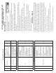
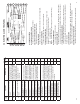
Fault
Code
Explanation Possible Causes
PLC
Select
1M
PLC
Select
2M
41
Slow wheel recovery on Red valve
channel.
For a 2M System, verify sensor and
valve wiring/plumbing is correct.
(See Side-By-Side and Axle-By-Axle
confi gurations). Slow brake release,
foundation brake mechanical faults,
dry bushings, broken ABS valve,
restricted piping. Check for kinks
and blockage etc., incorrect
air-lines, wiring.
X
42
Slow wheel recovery on Blue valve
channel.
X
43
Slow wheel recovery on Yellow valve
channel.
X
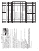
61
Hold solenoid Open circuit on Red
valve channel.
Modulator valve solenoid failure,
solenoid connection or valve cable
damage. The most likely causes
include: a bad solenoid or a loose
solenoid connection. Disconnect the
indicated solenoid and check the
resistance at the solenoid pins.
Check the female terminals on the
connector for excessive pin spread
or corrosion. Replace defective
hardware as required and retest.
X
62
Hold solenoid Open circuit on Blue
valve channel.
X
63
Hold solenoid Open circuit on Yellow
valve channel.
X
67
Dump solenoid Open circuit on Red
valve channel.
X
68
Dump solenoid Open circuit on Blue
valve channel.
X
69
Dump solenoid Open circuit on
Yellow valve channel.
X
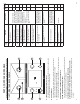
71
Hold solenoid Short circuit to ground
on Red valve channel.
Modulator valve solenoid failure or
value cable damage. The most likely
causes include: a damaged cable
or solenoid. An example of this is
a worn or chafed cable that has
exposed wires contacting the trailer.
Disconnect the indicated solenoid
and check the resistance at the
solenoid pins.
X
72
Hold solenoid Short circuit to ground
on Blue valve channel.
X
73
Hold solenoid Short circuit to ground
on Yellow valve channel.
X
77
Dump solenoid Short circuit to
ground on Red valve channel.
X
78
Dump solenoid Short circuit to
ground on Blue valve channel.
X
79
Dump solenoid Short circuit to
ground on Yellow valve channel.
X
9
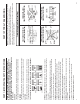
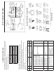
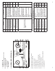
3.2 ELECTRICAL CONTROL PANEL
A. LCD MENU SCREEN
B. LCD MENU CONTROL KNOB
Knob activates all menu options and modes.
C. BLUETOOTH
®
PAIRED INDICATOR
Steady blue light indicates paired device.
D. CONTROL KNOB
Knob activates all electrical test modes and circuits to be diagnosed.
E. CIRCUIT INDICATORS
The small green LEDs illuminate or blink in testing phase.
F. POWER SOURCE SWITCH
Select between Internal Battery, External Power or Power Off.
Center: OFF (battery charge in this position only)
Left: Installed Battery ON
Right: External Power ON (power supply is an optional accessory)
G. TABLET CHARGE PORT
For charging tablet. Not a data port.
H. GROUND INTEGRITY
Solid green LED indicates good ground. Blinking red LED indicates a bad/
poor ground. Ground integrity is automatically verifi ed when power is turned on.
I. TROUBLE WARNING INDICATORS
Flashing red LEDs indicate problems that may exist in a selected circuit. This
includes the Overload Indicator, Open Circuit Indicator and Reversed (Battery)
Polarity Indicator.
J. VOLTAGE INDICATOR
Green LCD indicates fully charged battery. Amber LED indicates battery will need
charge soon. Red LED indicates battery needs charge immediately.
K. REVERSE POLARITY INDICATOR
Indicates when battery leads need to be switch due to reversed polarity.
A
B
D
C
E
F
H
G
I
J
K
L
M
N