
Product Manual

4
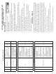
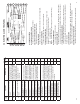
PART 1: IMPORTANT SAFETY INSTRUCTIONS
IT IS IMPORTANT TO READ, UNDERSTAND AND FOLLOW ALL SAFETY
MESSAGES AND INSTRUCTIONS PRINTED IN THIS MANUAL AND ON THE
EQUIPMENT BEFORE OPERATING. IF SAFETY INFORMATION IS NOT
HEEDED, SERIOUS INJURY OR DEATH TO THE OPERATOR OR BYSTANDERS
MAY OCCUR.
DANGER
Indicates a hazardous situation, if not avoided, will result in death or serious injury.
The possible hazards are shown in the adjoining symbols or explained in the text.
WARNING
Indicates a hazardous situation, if not avoided, could result in death or serious injury.
The possible hazards are shown in the adjoining symbols or explained in the text.
CAUTION
Indicates a hazardous situation, if not avoided, may result in minor or major injury.
The possible hazards are shown in the adjoining symbols or explained in the text.
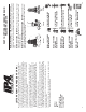
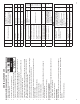
THE FOLLOWING SAFETY ALERT SYMBOLS ARE USED IN THIS MANUAL.
SYMBOL 1: Potential burn hazard. Sparks from electrical shorts can ignite
fl ammable liquids such as fuel or oil. Heat from electrical overloads can cause
fi re hazards.
SYMBOL 2: Potential electrical hazard. Batteries have enough electrical
energy potential to ignite fl ammable liquids such as fuel or oil. Wire overloads
can cause electrical failures. Shock hazard exists.
SYMBOL 3: Potential explosive air hazard. Pneumatic pressures used with
this equipment can cause explosive failures on damaged equipment.
SYMBOL 4: Potential eye hazard. Wear OSHA approved safety glasses.
Battery acid and high air pressures create hazardous situations for eyes.
SYMBOL 5: Potential chemical burn hazard. Wear protective gloves. Battery
acid is corrosive and can cause skin damage.
SYMBOL 6: Potential electrical hazard. Electrical energy can cause heat and
burn hazards.
SYMBOL 7: Potential fi re hazard. Use caution with fl ammable liquids such as
fuel and oil. Electrical shorts can ignite fl ammable liquids and wiring.
SYMBOL 8: Important information is stated.
37
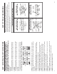
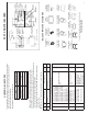
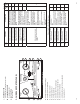
PART 10: TYPICAL TRAILER WIRING
Note: The standard wiring pictured below is viewed from the front of the connector.
Not all trailers/vehicles are wired to this standard. The use of an electrical
circuit tester is necessary to ensure proper match of vehicle’s wiring to trailer’s
wiring. On some trailers with 6-way round plugs, the 12V wire and electric brake wire
may be reversed (particularly horse trailers).
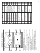
Trailer Wiring (View From Front Plug)
GROUND
12 VOLT AUX (12V)
LEFT TURN
(LT) & STOP
ELECTRIC
BRAKE (EB)
TAIL & RUNNING
LIGHTS (TM)
RIGHT TURN
(RT) & STOP
GROUND (GD)
CLEARANCE
(GL-MARK)
AUX (ABS)
LEFT TURN
(LTS)
STOP/BRAKE
(STOP)
TAIL/TAG
(GL-TAIL)
RIGHT TURN
(RTS)
GROUND
BACK-UP
LIGHTS (BU)
12 VOLT
(12V)
LEFT TURN
(LT)
ELECTRIC
BRAKE (EB)
TAIL LIGHTS
(TM)
RIGHT TURN
(RT)
GROUND
RIGHT TURN
& BRAKES (RT)
TAIL LIGHTS
(TAIL)
LEFT TURN
& BRAKES (LT)
AUX
(A)
6-WAY ROUND PIN VEHICLE
FEMALE SOCKET (FRONT VIEW)
7-WAY ROUND (J560)
FEMALE SOCKET (FRONT VIEW)
7-WAY SPADE/FLAT VEHICLE
FEMALE SOCKET (FRONT VIEW)
4/5-WAY FLAT VEHICLE
CONNECTION (FRONT VIEW)