
Product Manual

18
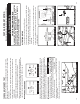
7.2 GROUND INTEGRITY TEST
Each time the MUTT
®
is powered on, it automatically runs a Ground Integrity Test.
A good ground connection must be established for the MUTT
®
to operate a trailer’s
electrical system.
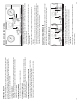
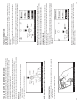
1. Immediately after power up, the green lights around the Control Knob will illuminate.
2. A solid/healthy ground connection is indicated by a steadily illuminated Ground
Integrity Indicator.
3. Bad/poor ground or bad cable condition is indicated by all of the LEDs blinking
simultaneously. See ESTABLISHING A CHASSIS GROUND below.
4. When one or more green circuit LEDs blink while the Ground Integrity Indicator
is steadily illuminated, it indicates that a solid ground has been established, but an
open circuit has been detected. Refer to OPEN CIRCUIT on pg. 19.
CHASSIS AND PIN GROUNDS
A poor ground warning may be an indication that the connected trailer is only wired
for chassis ground. There are two ground types. 1) Pin Ground: The ground wire
from each light assembly is wired through the main harness up into the trailer plug.
2) Chassis Ground: The ground wire from each light assembly is grounded directly to
the trailer chassis. Ground with the truck is established at the king pin.
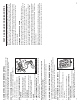
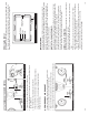
ESTABLISHING A CHASSIS GROUND
1. To simulate the king pin on a chassis ground
connection and bypass the ground integrity fault,
plug the supplied 10' Chassis Ground Cable into
the MUTT
®
’s Chassis Ground Outlet.
2. Using the alligator clip, attach the other end of the Chassis Ground Cable to the
chassis of the trailer.
3. Be sure that you are attaching to a clean, dry metal for an effective ground.
GOOD GROUND BAD/POOR GROUND
Plug the Chassis Ground Cable into the Outlet
DO NOT
Assume That a Bad Ground
Warning is a Result of a
Faulty Trailer. Check Cable
Connection.
23
PART 8: AIR BRAKE TESTING
Complete the pretesting checklist prior to all testing procedures.
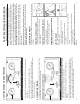
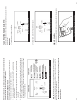
8.1 TESTING SET-UP
1. Push the Power Source Switch to the OFF position.
2. Set both Emergency and Service-Side Air Ball Valves to the CLOSED position.
3. Attach gladhand hoses from the MUTT
®
directly to your trailer’s air system,
securing the red hose to the Emergency Side and the blue hose to the
Service Side.
4. Connect your shop air to the Shop Air Inlet on the left-hand side of the tester.
5. Listen for any air leaks where the shop air connects to the tester, to avoid
erroneous results.
Set Emergency and Service Valves to CLOSED
DANGER
CHOCK TRAILER WHEELS
WARNING!!! DO NOT CONNECT SHOP AIR UNTIL COMPLETING
THE TESTING SET-UP PROCEDURE. FAILURE TO FULLY
UNDERSTAND THESE WARNINGS CAN RESULT IN MINOR TO
SERIOUS INJURY AND POSSIBLY DEATH.
!
!
Connect the Shop Air to the Shop Air Inlet
Push Power Source Switch to OFF
Attach Gladhand Hoses