
Product Manual

24
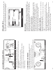
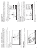
8.3 LEAK DOWN TESTING
You must always test the Emergency Side before testing the Service Side. Trying to
test the Service Side fi rst will result in erroneous readings.
EMERGENCY-SIDE LEAK DOWN TESTING
1. After setting the desired working pressure, set the Emergency-Side Air Ball Valve
to the CLOSED position. This will begin the leak down test.
2. Observe the needle on the air gauge and note any PSI drop after pressure
stabilizes.
3. Look for air loss according to your local specifi cations by noting consistent air
drop over time. If air pressure continues to drop at an unacceptable rate, you can
turn your air supply back on by setting the Emergency-Side Air Ball Valve to OPEN
and attempt to fi nd the source of the leak in the air system.
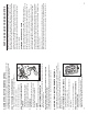
Set Emergency-Side Air Ball Valve to CLOSED
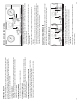
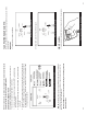
8.2 SETTING DESIRED WORKING PRESSURE
1. Turn the MUTT
®
on by selecting BATTERY or EXTERNAL power with the Power
Source Switch.
2. Set the Emergency-Side Air Ball Valve to the OPEN position.
3. Turn Air Regulator Knob clockwise or counterclockwise until needle on the
Emergency-Side Air Gauge points to the desired operating pressure. (Most shops
prefer 80-100 psi during testing.)
Set Emergency-Side Air Ball Valve to OPEN, Turn Regulator to Desired PSI
17
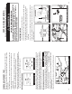
PART 7: ELECTRICAL/LIGHTING TESTING
Complete the pretesting checklist prior to all testing procedures.
The MUTT
®
is microprocessor controlled and features a special diagnostic
fi rmware, designed to seamlessly integrate with your preferred methods of testing.
The MUTT
®
will power the selected electrical circuits and instantly alert you to any
signs of a faulty condition. To properly utilize the diagnostic features, a complete
scan of the trailer’s electrical system should be performed at the front of the
trailer using the MUTT
®
prior to a walk-around inspection. If any wiring faults are
present, the MUTT
®
will blink or sound, alerting you to the issue. Only a one-time,
walk-around/visual inspection is needed to confi rm that each individual light bulb is
properly illuminating.
NOTE: Some advanced functions may not be listed on the face panel, so it’s
important to read the manual in its entirety to ensure that you are getting the
full use of this diagnostic system.
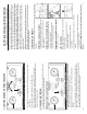
7.1 SELECTING A CIRCUIT
Circuits can be selected for testing manually, via remote control or by initiating Auto
Cycle Mode.
OPERATING WITH MANUAL CONTROL
1. Turn the Control Knob to select a circuit. The Control
Knob is automatically set to Ground Integrity when
power is turned on.
OPERATING WITH THE REMOTE CONTROL
1. Press and release the Up Arrow to select the next
circuit in a clockwise rotation.
2. Press and release the Down Arrow to select the
next circuit in a counterclockwise rotation.
OPERATING WITH THE BLUETOOTH
®
TABLET
1. See Section 6.5 on pg. 15.
AUTO CYCLE MODE
Auto Cycle Mode automatically tests one circuit at a time
in a clockwise rotation.
1. Press and release the Control Knob. The AUX 2
Indicator should illuminate.
2. A fi ve second delay commences between
circuit sections.
3. Circuits are automatically tested one at a time in a clockwise
rotation.
4. To cancel Auto Cycle Mode, momentarily press and release or
by rotating the Control Knob.
NOTE: Auto Cycle Mode does not work when ABS or Brake Light Circuits are
selected.