
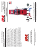
Product Manual

10
L. HAZARD BUTTON
Activates the four-way fl ashers on trailer.
M. 30 AMP FUSE SOCKET
Overload protection.
N. MUTE BUTTON
Mute all alerts.
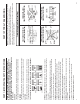
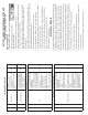
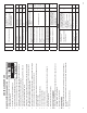
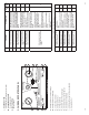
3.3 AIR BRAKE CONTROL PANEL
A. Emergency-Side Air Pressure Gauge
B. Emergency-Side Air Ball Valve
C. Chassis Ground Outlet
D. Emergency-Side Out
E. Air-Regulator Knob
F. Service-Side Air Pressure Gauge
G. Service-Side Brake Control Switch
H. Service-Side Air Ball Valve
I. USB Data Port (used for fi rmware updates)
J. Service-Side Out
LEAK DOWON TEST (Emergency/Service): To charge syste
ZLWKDUHVHWVZLWFKWRRSHQğOOWRGHVLUHGSUHVVXUH
&ORVHVZLWFKWRVKXWRIIDLUĠRZDQGQRWHDQ\SUHVVXUH
GURSWKURXJKQHHGOHPRYHPHQW
7$.(&$87,212SHQHPHUJHQF\VLGHVZLWFKWRUHOHDVH
SDUNLQJEUDNH2SHQVHUYLFHVLGHVZLWFKWRDFWXDWHVHUYLFH
EUDNHV7RRSHUDWHVHUYLFHEUDNHVZLWKUHPRWHVHWVZLWFK
WRH[KDXVWUHPRWHDQGSUHVVVPDOOEXWWRQRQUHPRWHFRQWURO
CLOSED
psi
0
20
40
60
80
100
120
140
160
CLOSED
EXHAUST
CHASSIS GROUND
EMERGANCY SIDE OUT SERVICE SIDE OUT
USB DATA PORT
EMERGENCY
SIDE
SERVICE
SIDE
EXHAUST
REMOTE
PULL KNOB TO ADJUST
0$;36,
WARNING: CHOCK ALL TRAILER WHEELS
BEFORE APPLYING AIR PRESSURE
AIR BRAKE CONTROLS
PRESSURIZE
OPEN OPEN
psi
0
20
40
60
80
100
120
140
160
INLET AIR PRESSURE IS DISPLAYED ON
(0(5*(1&<6,'(*8$*(7RVHWSUHVVXUH
FRQQHFWVKRSDLUSXVKVZLWFKWRRSDQ
WKHDGMXVWUHJXDOUNQRE
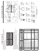
Air Brake Control Panel
A
C
D
I
J
B
G
F
H
E
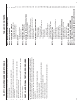
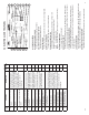
31
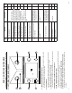
Fault
Code
Explanation Possible Causes
PLC
Select
1M
PLC
Select
2M
21
Red channel wheel speed sensor
S1A has an erratic output voltage.
Loose sensor, connection, bracket or
exciter, damaged exciter, sensor is not
properly adjusted or has worn cable
insulation or worn sensor block clip,
wheel bearing failure, wheel bearing
is not properly adjusted (these faults
will only occur at speeds greater than
6 mph).
Measure the AC voltage at the sensor
in question while rotating the wheel at
a rate of about one rotation every two
seconds. The output should be at least
200 millivolts (0.2V AC).
If this is not the case, push in the sensor
until it touches the exciter and rotate
the wheel again. If this doesn’t correct
the problem, then the sensor should be
replaced.
Verify the tire and wheel size is large
enough for 100 tooth exciter ring.
If these faults re-occur at the same
speed, inspect the exciter ring for
damage.
Smaller wheels and tires require 80
tooth exciter rings. Reference Tire Scale
Factor Chart.
Verify sensor and valve wiring/plumbing
is correct.
See side-by-side and axle-by-axle
confi gurations.
X
22
Red channel wheel speed sensor
S1B has an erratic output voltage.
X
23
Blue channel wheel speed sensor
S2A has an erratic output voltage
X
24
Yellow channel wheel speed
sensor S2B has an erratic output
voltage.
X
25
Blue channel wheel speed sensor
S3A has an erratic output voltage.
X
26
Yellow channel wheel speed
sensor S3B has an erratic output
voltage.
X
31
Auxiliary channel 1 fault (digital
channel 1) output only.
PLC Select 2M Plus (ABS
Auxiliary Codes).
Note:
These Codes are only used with PLC
Select 2M Plus ABS that supports
trailer Auxiliaries.
Auxiliary Channel has an open circuit
or the ECU (Electronic Control Unit)
has an auxiliary device connected
and is not programmed to be.
Note: These codes do not affect ABS
performance and do not illuminate
the tractor trailer ABS warning
lamps.
32
Auxiliary channel 2 fault (digital
channel 2) output only.
33
Auxiliary channel 3 fault (digital
channel 3) output only.
34
Auxiliary channel 4 fault (digital
channel 4) output only.
35
Auxiliary channel 5 fault (digital
channel 5) output only.
Occurs Only When Vehicle is Stationary