
User's Manual
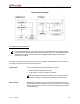


TABLE OF CONTENTS
M1617-12_FCCRpt.doc Page 3
SECTION 1: THEORY OF OPERATION ................................................................................. 4
General Block Diagram................................................................................................ 4
General Block Diagram Definitions
..................................................................... 4
M1617-12 Mobile Radio Section Descriptions ........................................................... 6
Microcontroller
.................................................................................................... 6
Support Circuitry ................................................................................... 6
Inputs/Outputs
.................................................................................................... 6
Modem
.............................................................................................................. 7
VLogic and Digital Ground
................................................................................. 7
Receiver 1 Front-End
......................................................................................... 8
Receiver 1 IF
...................................................................................................... 8
Transmit Modulation
........................................................................................... 8
Injection Synthesizer
.......................................................................................... 9
Transmitter/TR Switch
........................................................................................ 9
Power and Analog Ground
................................................................................. 9
SECTION 2: FACTORY TEST PROCEDURE ....................................................................... 10
Equipment List ........................................................................................................... 10
Programming and Configuring Mobile Radio.......................................................... 11
Adjustment / Alignment Procedures ........................................................................ 12
Receiver Injection
............................................................................................. 12
Receiver 1
........................................................................................................ 12
Receiver 2
........................................................................................................ 13
Transmit Data
................................................................................................... 14
Transmit Power Control
.................................................................................... 15
Receive Data
.................................................................................................... 16
Final Test
.......................................................................................................... 17
Uplink Hardware Timing Verification
................................................................ 17
Downlink Hardware Timing Verification
............................................................ 19
SECTION 3: FCC LABEL AND LABEL PLACEMENT ......................................................... 21
M1617-12 Mobile Radio FCC Label Placement ........................................................ 21
M1617-12 Mobile Radio FCC Label........................................................................... 21
APPENDIX A: M1617-12 CIRCUIT BOARD DIAGRAMS ..................................................... 22
APPENDIX B: M1617-12 TEST DATA SHEET ..................................................................... 23