
User Manual

SECTION 1: THEORY OF OPERATION
~\Technical Documentation\System Manuals\FCC-Reports\IP8HPV\IP8HPV-FCCRpt.doc Page 4
Low Side Injection In the receive mode, the synthesizer provides a local oscillator signal of 45
MHz below the selected receive channel frequency.
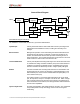
Baseband Routing Allows the microcontroller to select one of the two diversity receiver audio
outputs for demodulation by the modem. Switching is done by the
microcontroller comparing the Received Signal Strength Indication (RSSI)
outputs from each receiver. Provision is also made for switching an
external modulation source from the DB9 data connector to the transmitter
input.
Transmitter/TR Switch Consists of an exciter and power amplifier module. The transmitter
circuitry includes a T/R switch switching the antenna between transmitter
and receiver 1 (TX/RX1).
Receiver 1/Receiver 2 Required to support the mobile DRS; two (2) discrete receivers are tuned
to the same channel and use two (2) antennas.
The receivers are double-conversion superheterodyne with a first
Intermediate Frequency (IF) of 45 MHz and a second IF frequency of 455
KHz. Each receiver consists of bandpass filters, an RF amplifier, a crystal
filter, a double-balanced mixer, and a one-chip IF system. The injection
synthesizer provides the first local oscillator signal. Outputs from each
receiver include RSSI and analog audio for the baseband routing circuitry
and modem.
Power Supply Consists of circuitry that derives the various operating voltages for the
radio. A group of fixed and adjustable voltage regulators are used for this
purpose. The transmitter power control circuitry is also found in this
section.