TECHNICAL DESCRIPTION APCO P25 EZPRO25 RF – INSTALLATION GUIDE
INSTALLATION GUIDE Code: Installation Guide EZPRO25 RF.do Date: 12/18/2007 Page: 2 of 21 INDEX 1. INTRODUCTION 3 2. UNPACKING AND CHECKING 5 3. PREVIOUS CONSIDERATIONS 5 4. INFORMATION ON SAFETY AND ELECTROMAGNETIC COMPATIBILITY 5 5. EQUIPMENT DESCRIPTION 6 5.1 FRONT VIEW 7 5.2 REAR VIEW 8 5.3 MODULES 9 5.4 CABLING AND CONNECTORS 13 INSTALLATION GUIDE 14 6.1 LOCATION 14 6.2 POWER SUPPLY CONNECTION 14 6.3 ANTENNA CONNECTION 15 6.
INSTALLATION GUIDE Code: Installation Guide EZPRO25 RF.
INSTALLATION GUIDE Code: Installation Guide EZPRO25 RF.do Date: 12/18/2007 Page: 4 of 21 1. INTRODUCTION The EZPRO25 RF module (Base Station Repeater) are a modular design, high performance products used as APCO repeaters. The radio system is available in the 806-870Mhz frequency band. The proper functioning of any electronic device depends on its correct use. It is therefore recommended that the instructions in this manual be followed.
Code: Installation Guide EZPRO25 RF.do INSTALLATION GUIDE Date: 12/18/2007 Page: 5 of 21 2. UNPACKING AND CHECKING The following elements are supplied in the box: EZPRO25 RF 2 cables SMB RF Installation manual The equipment is supplied with all the modules already assembled in the rack and with the RF cables connected. The modules in the basic configuration are: Control (RCPU P25), Transmitter (RTX P25), power module (RPA P25), Receiver (RRX P25) and the power supply module (RPS P25).
INSTALLATION GUIDE Code: Installation Guide EZPRO25 RF.do Date: 12/18/2007 Page: 6 of 21 These standards ensure the essential requirements established in article 3 of directive 1999/5/CE. In any case, take the following points into consideration: ! Most electronic equipment is susceptible to electromagnetic interference if it is not duly protected. If the EZPRO25 RF is placed near unprotected electronic devices, they may malfunction.
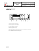
Code: Installation Guide EZPRO25 RF.do INSTALLATION GUIDE Date: 12/18/2007 Page: 7 of 21 5. EQUIPMENT DESCRIPTION 5.1 FRONT VIEW ♦ EZPRO25 RF 1 7 2 3 4 5 6 1.- RPS P25 (Repeater Power Supply) 2.- RPA P25 (Repeater Power Amplifier) 3.- RTX P25 (Repeater Transmitter) 4.- RRX P25 (Repeater Receiver) 5.- Option RRX2 P25/BSYNC P25 ( Repeater Receiver 2 / EZPRO25 RF Synchronism) 6.
INSTALLATION GUIDE Code: Installation Guide EZPRO25 RF.do Date: 12/18/2007 Page: 8 of 21 5.
INSTALLATION GUIDE Code: Installation Guide EZPRO25 RF.do Date: 12/18/2007 Page: 9 of 21 5.3 MODULES 1. RPS P25 (REPEATER POWER SUPPLY) LEDs to indicate module status. LED TYPE SUPPLY Green NORMAL STATUS On 24V or 26.4V Green On 13.2V Green On FUNCTIÓN There are 26.4V at the RPS P25 input There are 26.4V at the RPS P25 output There are 13.2V at the RPS P25 output Power on switch (Ref. 7): ON/OFF switch to connect to and disconnect from the EZPRO25 RF 2.
INSTALLATION GUIDE Code: Installation Guide EZPRO25 RF.
Code: Installation Guide EZPRO25 RF.do INSTALLATION GUIDE Date: 12/18/2007 Page: 11 of 21 4. RRX P25 (REPEATER RECEIVER) LEDs to indicate module status. ON LED TYPE Green NORMAL STATUS FUNCTIÓN On Power supply correct REF. ERROR Red Off Failure in the 10 MHz reference INT. ERROR Red Off Internal failure BBSR ERROR Red Off Communication failure with the RCPU P25 module 5. SLOT OPTION: RRX2 / BSYNC (REPEATER RECEIVER 2/ BSR SYNCHRONISM) LEDs to indicate the status of option RRX2.
INSTALLATION GUIDE Code: Installation Guide EZPRO25 RF.do Date: 12/18/2007 Page: 12 of 21 6. RCPU P25 (REPEATER CONTROL) LEDs to indicate the module status. LED ON REF. ERROR INT.
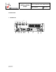
Code: Installation Guide EZPRO25 RF.do INSTALLATION GUIDE Date: 12/18/2007 Page: 13 of 21 5.4 CABLING AND CONNECTORS ♦ BSR75 8.- Power supply connector. 9.- Transmission power antenna connector. 10.- SMB RF cables. 11.- Reception antenna connector (receiver chain 1) 12.- Reception antenna connector (receiver chain 2) 13.- Reception antenna connectors for the RRX2 P25 option / antenna connectors for the GPS, depending on the inserted module. 14.- Ethernet B connector. 15.- Ethernet A connector. 16.
Code: Installation Guide EZPRO25 RF.do INSTALLATION GUIDE Date: 12/18/2007 Page: 14 of 21 6. INSTALLATION GUIDE The following recommendations must be followed closely before starting up the EZPRO25 RF module. 6.1 LOCATION The EZPRO25 RF have been designed in the standard format of 19” / 3 units high, and so they must be installed in cabinets with this format. The EZPRO25 RF site must be permanent, well-ventilated and without vibrations. 6.
INSTALLATION GUIDE Code: Installation Guide EZPRO25 RF.do Date: 12/18/2007 Page: 15 of 21 6.3 ANTENNA CONNECTION Choose the most adaptable antenna for the installation. The antenna must have an impedance of 50 ohms to the equipment transmission frequency. Install the antenna in accordance with the manufacturer’s instructions. Use a cable coaxial, avoiding as much as possible large cable lengths. Cable impedance is 50 ohms. Measure the ROE of the installation.
INSTALLATION GUIDE Code: Installation Guide EZPRO25 RF.do Date: 12/18/2007 Page: 16 of 21 7. CONFIGURATION A EZPRO25 RF is configured via an NMS (Network Management System). To configure the EZPRO25 RF, consult the NMS manual. 8. INCIDENTS The repeater must be repaired by authorized technical personnel only. If a EZPRO25 RF failure occurs, the entire EZPRO25 RF must be replaced.
INSTALLATION GUIDE Code: Installation Guide EZPRO25 RF.do Date: 12/18/2007 TX POWER Initial Release Revision: 00 OFF Page: 17 of 21 No power transmission in the antenna. Wait for EZPRO25 RF to be started up by the CNC. Check other LED indications. Contact Technical Services if unsolved.
INSTALLATION GUIDE Code: Installation Guide EZPRO25 RF.do BSYNC P25 RRX P25 RTX P25 Date: 12/18/2007 ON OFF REF. ERROR ON INT. ERROR BBSR ERROR ON ON RPA P25 ERROR ON RPW ERROR ON ON OFF REF. ERROR ON INT. ERROR BBSR ERROR ON ON ON OFF REF. ERROR OFF TIME GPS OFF Initial Release Revision: 00 Page: 18 of 21 INTERNAL POWER SUPPLY FAILURE. CONTACT TECHNICAL SERVICES. Failure in the 10MHz reference. Contact Technical services. Internal failure. Contact Technical services.
INSTALLATION GUIDE Code: Installation Guide EZPRO25 RF.do Date: 12/18/2007 PPS GPS OFF Page: 19 of 21 IF GPS IS ACTIVATED, THERE IS FAILURE IN THE PPS SIGNAL OF THE GPS: - CHECK THAT THE STARTING UP PERIOD HAS BEEN EXCEEDED (ABOUT 10 MINUTES AFTER SWITCHING ON) - CHECK THE GPS ANTENNA CONNECTION. - CHECK THE CORRECT POSITIONING OF THE GPS ANTENNA, IN ACCORDANCE WITH THE MANUFACTURER’S INSTRUCTIONS. CONTACT TECHNICAL SERVICES IF STILL UNSOLVED.
INSTALLATION GUIDE Code: Installation Guide EZPRO25 RF.do Date: 12/18/2007 ON OFF REF ERROR ON INT ERROR BBSR ERROR RCPU P25 DIV ERROR CNC ERROR RX ETH LINK1 ETH LINK2 ETH RX ETH TX Initial Release Revision: 00 Page: 20 of 21 INTERNAL POWER SUPPLY FAILURE. CONTACT TECHNICAL SERVICES. Failure in the 10MHz reference. Check that the BSYNC P25 module is installed or that the SYNC IN cable is correctly connected. Contact Technical services if still unsolved. ON Internal failure.
INSTALLATION GUIDE Code: Installation Guide EZPRO25 RF.do Date: 12/18/2007 Page: 21 of 21 8.2 ALARMS WITHOUT STATUS LEDS 8.2.1 Interference at the bsr. This alarm is monitored in APCO P25 Network Management System (NMS). See “APCO P25 Event List” in NMS help. An interference in the EZPRO25 RF is activated when a high number of invalid consecutive receptions occurs at a EZPRO25 RF.