
User's Manual

SECTION 4: FACTORY TEST PROCEDURE
489288.DOC Page 10
Adjustment / Alignment Procedures
Make appropriate notations of any items that require attention during this procedure. This information is
needed later during the repair process.
Startup
Step 1 Remove the base station cover placing the screws in a location where they will not be
misplaced.
Step 2 Connect the base station to the appropriate components.
Step 3 Power up the base station and computer. The power supply ammeter must read 1.2
amps or less with a 13.8 VDC input.
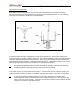
Receiver Injection
Step 1 Connect the base station to gps antenna and wait until the frequencies of OCXO and
VCTCXOs are corrected and the error is below 0.1 ppm. You can check the error by
typing gpsstatus.
Step 2 Using the high frequency prob,at AL7 check the amplitude of the signal. The amplitude
of the injection frequency should read approximately 0 dBm ±1 dBm.
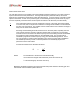
Receiver
Step 1 Using the high frequency probe, monitor the 44.545 MHz second injection frequency
at AU4 pin 3, adjust trimmer capacitor (C22) to the center of the oscillator’s oscillation
range. The amplitude level of pin 3 of AU4 should read between +5 and +10 dBm.
Step 2 Inject an on-frequency signal at a level of –80 dBm, modulated with a 1 KHz test tone at
±5.0 KHz deviation into the receiver under test.
Step 3 Check the receiver’s sensitivity, verifying that the SINAD is 12 dB or better at a maximum
level of –119 dBm (-120 is typical).