
Installation Instructions
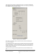
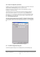
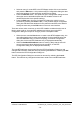
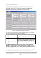
Table Of Contents
- nanoBTS Installation and Test Manual
- 1 Introduction
- 2 Overview
- 3 Customer safety and regulatory information (CENG0133)
- 4 BTS Hardware Installation (CENG0210)
- 5 PSU Installation Guide (CENG0033)
- 6 BTS Installer User Guide (CENG0048)
- Introduction
- 6.2 Capabilities
- 6.3 Concepts
- 6.4 Getting Started
- 6.5 User Interface Reference
- 6.6 The DHCP Server
- 6.7 BTS Attribute Reference
- 6.7.1 The BTS Configuration Dialog box
- 6.7.2 Current Values Display
- 6.7.3 Identifying a nanoBTS
- 6.7.4 How Defaults Work
- 6.7.5 Enabling Configuration Phases
- 6.7.6 The BTS tab
- 6.7.7 The DHCP tab
- 6.7.8 The Unit ID tab
- 6.7.9 The NV Attr (1) tab
- 6.7.10 The NV Attr (2) tab
- 6.7.11 The NV Attr (3) tab
- 6.7.12 The NV Attr (4) tab
- 6.7.13 The Download tab
- 6.8 Using Network Listen
- 6.9 Using BTS Installer via a proxy
- 6.10 Connecting to a nanoBTS via SSL
- 6.11 Configuration File Reference

© ip.access Ltd
COMPANY CONFIDENTIAL CENG0336_XE_nanoBTS_Installation_and_Test_Manual.doc
- 72 -
If the unit’s Up Time is equal to or greater than 24 hours, or if a warning message has
been displayed and the user has selected the OK button, the Frequency Control dialog
box is displayed, as shown in Figure 44 below.
Figure 44 - Frequency Control dialog box
BTS Installer automatically reads from the BTS all of the values for this dialog box
when it is first displayed.
The Timing Bus group box contains read-only information about clock sources and the
status of the timing bus. It contains a Refresh button, which when clicked causes BTS
Installer to fetch the latest values for clock sources and status from the nanoBTS and
update the display as necessary.
The Clock Sources group box lists the possible clock sources and indicates for each
one: