
Installation Instructions
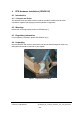
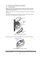
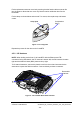
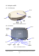
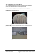
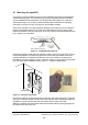
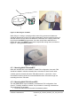
Table Of Contents
- nanoBTS Installation and Test Manual
- 1 Introduction
- 2 Overview
- 3 Customer safety and regulatory information (CENG0133)
- 4 BTS Hardware Installation (CENG0210)
- 5 PSU Installation Guide (CENG0033)
- 6 BTS Installer User Guide (CENG0048)
- Introduction
- 6.2 Capabilities
- 6.3 Concepts
- 6.4 Getting Started
- 6.5 User Interface Reference
- 6.6 The DHCP Server
- 6.7 BTS Attribute Reference
- 6.7.1 The BTS Configuration Dialog box
- 6.7.2 Current Values Display
- 6.7.3 Identifying a nanoBTS
- 6.7.4 How Defaults Work
- 6.7.5 Enabling Configuration Phases
- 6.7.6 The BTS tab
- 6.7.7 The DHCP tab
- 6.7.8 The Unit ID tab
- 6.7.9 The NV Attr (1) tab
- 6.7.10 The NV Attr (2) tab
- 6.7.11 The NV Attr (3) tab
- 6.7.12 The NV Attr (4) tab
- 6.7.13 The Download tab
- 6.8 Using Network Listen
- 6.9 Using BTS Installer via a proxy
- 6.10 Connecting to a nanoBTS via SSL
- 6.11 Configuration File Reference

© ip.access Ltd
COMPANY CONFIDENTIAL CENG0336_XE_nanoBTS_Installation_and_Test_Manual.doc
- 29 -
2
Locking Spring
1
T
O
P
Figure 14 - Mounting the nanoBTS
When fixing to a ceiling or a sloping wall the same fixing process and clearances
should be observed as for fixing to a wall (at least 80mm from the bracket to the top of
wall and 120mm from the side of the bracket to a side wall). On a sloping surface the
top of the bracket MUST be uppermost. Once the unit has been attached to the
bracket the outer cover MUST be removed to expose the cooling vanes, as shown in
Figure 15 - Ceiling Mounted nanoBTS
Figure 15 - Ceiling Mounted nanoBTS
4.7.1 Mounting Multi-TRX nanoBTS
When the nanoBTS are to be installed in a Multi-TRX configuration, then each TRX
should be installed in a similar orientation but not closer than 30cm to each other.
A further specific constraint is that the TIB cables must be <1.5m and a 1.5mm
2
Chassis Bond cable must also be connected between each TRX with a length not
exceeding that of the TIB cable.
4.7.2 Mounting Multi-TRX 165 nanoBTS
The 165 (EDGE) BTS may be installed in a stacked two-TRX configuration. See
Annex A - Drawing 165#018 for details. The procedure for mounting a stacked two-
TRX configuration is as follows:
• Fit the first wall bracket to the wall in the desired position