
Instruction Manual
Page 3
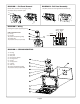
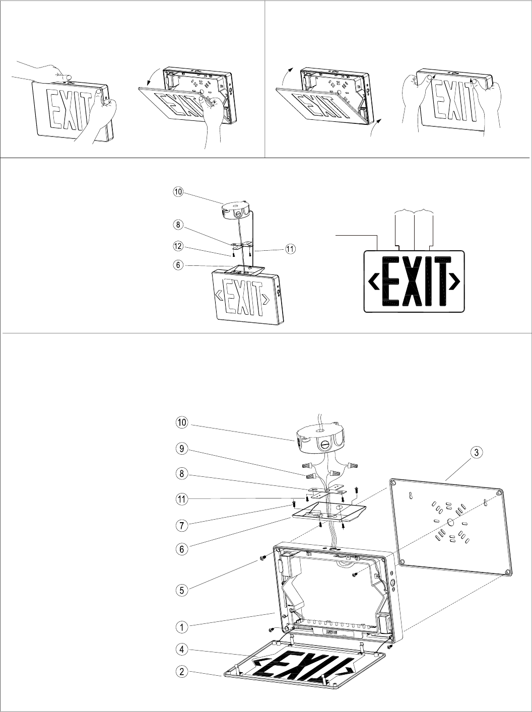
Remove EXIT panel from the housing by pulling
carefully at the top of the EXIT panel
Snap EXIT panel to the housing bottom first and then top
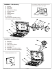
Holding wire supports sign during wiring
PARTS DESCRIPTION
6) Canopy
8) Crossbar
10) Juncon box (Building ulity)
11) Holding wire
12) Crossbar screws (not provided)
277VAC
INPUT
120VAC
INPUT
GREEN
GROUND WIRE
BLACK
WHITE
ORANGE
1) Housing
2) EXIT panel
3) Back plate
4) Red or Green diffuser
5) Housing screws
6) Canopy
7) Canopy screws
8) Crossbar
9) Wire nuts
10) Juncon box (Building ulity)
11) Crossbar screws (not provided)
DIAGRAM 1 - Exit Panel Removal DIAGRAM 2 - Exit Panel Assembly
DIAGRAM 3 - Wiring
DIAGRAM 4 - CEILING MOUNTING