
User's Manual


WA020100 - Smart Irrigation Controller
UMAOC001 Rev G
USER MANUAL
Page 7 of 33
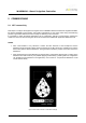
NOTE
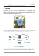
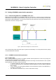
• To activate the electrovalve Watersens applies +9V or +12V (depending on model) in voltage A and
0V in voltage B.
• To deactivate the electrovalve the polarity of the output voltage is inverted (0V in voltage A and +9V or
+12V in voltage B)
Figure 5. Output pulse waveform for electrovalve excitation
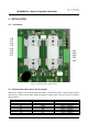
4.3 Sensors input wires (optional)
Watersens has the possibility to connect external sensors. There is a specific model with connections for this
purpose
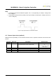
Connector
position
Wire color
Description
Electrical value
J8.1
Grey
Pulse input (input to connect an external pulse emitter
to the internal pulse counter - digital signal)
Range 0 – 3.3V
or
to connect an open collector
/ drain output
J8.2
Brown
Voltage reference for pulse input
0V
J8.3
White
RS485 communication output – signal A
From -7V to +12V
J8.4
Yellow
RS485 communication output – signal B
From -7V to +12V
J8.5
Green
Voltage reference for RS485 communication
0V