
User's Manual


WA020100 - Smart Irrigation Controller
UMAOC001 Rev G
USER MANUAL
Page 6 of 33
4 INSTALLATION
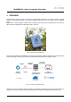
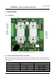
4.1 Connectors
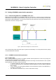
Figure 4. Connectors location in Watersens circuit
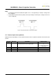
4.2 Electrovalve output wires (for all models)
Watersens is designed to be used with latch electrovalves. These devices require a short excitation pulse to
open/close the valve to flow the water. Watersens applies a positive pulse to open the valve and a negative
pulse to close it.
Connector position
Wire color
Description
J1.1
Brown
Output 1 – Voltage A
J1.2
Green
Output 1 – Voltage B
J1.3
Grey
Output 2 – Voltage A
J1.4
Yellow
Output 2 – Voltage B
J1.5
Pink
Output 3 – Voltage A
J1.6
Red
Output 3 – Voltage B
J1.7
White
Output 4 – Voltage A
J1.8
Blue
Output 4 – Voltage B
J8.1
J8.2
J8.3
J8.4
J8.5
J1.8
J1.7
J1.6
J1.5
J1.4
J1.3
J1.2
J1.1