
User's Manual

WA020100 - Smart Irrigation Controller
UMAOC001 Rev G
USER MANUAL
Page 14 of 33
7 DATA FRAME FORMATS
7.1 UPLINK FRAMES (FROM NODE TO SERVER)
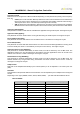
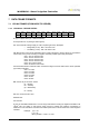
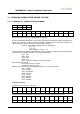
7.1.1 UPLINK 00 – DEVICE STATUS
byte 1
byte 2
byte 3
byte 4
byte 5
byte 6
byte 7
byte 8
byte 9
byte 10
byte 11
tf
te
mv
em
es
dd
hh
mm
ss
ti_hi
ti_lo
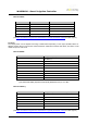
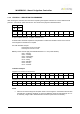
tf. Type of uplink frame (00 - Watersens status)
te. Temperature in ºC (data type 8 bits signed)
mv. microcontroller voltage supply in volts x10 (data type 8 bits). Examples:
Voltage OK (>2.9V) - mv = 33 means 3.3V
Low battery (<2.9V) - mv = 28 means 2.8V
em. Electrovalve control mode. Parameter which contains the flags to know if valves are controlled in
manual way or they work according to irrigation schedule (variable type mask). Examples:
0x01 – EV1 in manual mode
0x02 – EV2 in manual mode
0x04 – EV3 in manual mode
0x08 – EV4 in manual mode
0x0F - All in manual mode
0x00 - All valves in auto mode
es. Electrovalve status. Parameter which contains the flags to know the status of the valves (variable
type mask). Examples:
0x01 - EV1 ON.
0x02 - EV2 ON.
0x04 - EV3 ON.
0x08 - EV4 ON.
0x0F - All ON
0x00 - All OFF
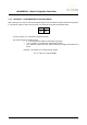
dd. Current day of the week. Values:
01 – Monday
02 – Tuesday
03 – Wednesday
…
07 - Sunday
hh. Hour in time format in 24H
mm. Minutes
ss. Seconds
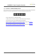
ti_hi-ti_lo. Timetable identification. To avoid long transmissions sending the irrigation timetable of all
valves, user can assign a code during setup process to identify the irrigation programmed in
Watersens. This code will be included in the status uplink frame to know what is the current irrigation
schedule.
Example - ti_hi = 01
ti_lo = 05
table_identifier = 1*256 + 5 = 261