WATERSENS USER MANUAL (model: WA020100 – SMART IRRIGATION CONTROLLER)
WA020100 - Smart Irrigation Controller 1 CONTENTS 1 2 3 4 CONTENTS ............................................................................................................................................................... 1 SAFETY PRECAUTIONS AND OTHER CONSIDERATIONS .............................................................................. 2 OVERVIEW ...................................................................................................................................................
WA020100 - Smart Irrigation Controller 2 SAFETY PRECAUTIONS AND OTHER CONSIDERATIONS General considerations: • • • • Incorrect handling or installation of the unit may result in injury to personnel as well as damage to the unit or other equipment associated with the system. Read the manual carefully prior to connecting the unit. Follow all installation and maintenance instructions throughout the unit’s working life. Pay special attention to the installation standards of the National Electrical Code.
WA020100 - Smart Irrigation Controller This radio transmitter [IC: 26883-WA0201] has been approved by Innovation, Science and Economic Development Canada to operate with the antenna types listed below, with the maximum permissible gain indicated. Antenna types not included in this list that have a gain greater than the maximum gain indicated for any type listed are strictly prohibited for use with this device.
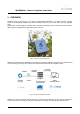
WA020100 - Smart Irrigation Controller 3 OVERVIEW Nowadays water is becoming in one of the more appreciated substances in our planet. Climatic changes, growth of the worldwide population and extreme weather make we must to care water as a very important good. Watersens is a smart irrigation controller able to manage several latch type electrovalves to save water for different types of applications as golf fields, parks, crops, etc Figure 1.
WA020100 - Smart Irrigation Controller Figure 3.
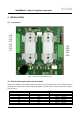
WA020100 - Smart Irrigation Controller 4 INSTALLATION 4.1 Connectors J1.8 J1.7 J1.6 J1.5 J1.4 J1.3 J1.2 J1.1 J8.1 J8.2 J8.3 J8.4 J8.5 Figure 4. Connectors location in Watersens circuit 4.2 Electrovalve output wires (for all models) Watersens is designed to be used with latch electrovalves. These devices require a short excitation pulse to open/close the valve to flow the water. Watersens applies a positive pulse to open the valve and a negative pulse to close it. Connector position J1.1 J1.2 J1.
WA020100 - Smart Irrigation Controller NOTE • To activate the electrovalve Watersens applies +9V or +12V (depending on model) in voltage A and 0V in voltage B. • To deactivate the electrovalve the polarity of the output voltage is inverted (0V in voltage A and +9V or +12V in voltage B) Figure 5. Output pulse waveform for electrovalve excitation 4.3 Sensors input wires (optional) Watersens has the possibility to connect external sensors.
WA020100 - Smart Irrigation Controller 5 COMMISSIONING NFC connectivity 5.1 First step is to configure the equipment to register in the LoRaWAN network and define the irrigation timetable. By default LoRaWAN communication and irrigation parameters are the values used during manufacturing process to guarantee Watersens works correctly for delivering to final customer. It is possible to modify the default parameters via any smartphone with NFC communication.
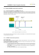
WA020100 - Smart Irrigation Controller 5.2 5.2.1 Setting LoRaWAN communication parameters Understanding Watersens LoRaWAN profile class Watersens can be integrated in a LoRaWAN network as a class A device. It means the device implements a bi-directional communication profile in which the data sent by server only can be received by the node after performing an uplink transmission. Is in this moment when the node opens two short receive windows for the downlink as it is shown in the figure below.
WA020100 - Smart Irrigation Controller Activation method Watersens can be configured in 2 different methods depending on user preferences (security, band occupancy time, etc) OTAA (Over The Air Activation Method). Watersens receive a device address and an authorization token from which to derive sessions keys in combination with AppKey parameter after sending a JOIN request to the server. This method provides high level of security. ABP (Activation By Personalization).
WA020100 - Smart Irrigation Controller Table for US915 DataRate Configuration Indicative physical bit rate [bit/s] 0 SF10 / 125kHz 980 1 SF9 / 125kHz 1760 2 SF8 / 125kHz 3125 3 SF7 / 125kHz 5470 5:7 RFU (visit https://lora-alliance.org/resource-hub/lorawanr-regional-parameters-v102rb for other regions) Tx Power The output power can be adjusted according to tables below depending on the region (EU868, US915 or AS923).
WA020100 - Smart Irrigation Controller Tx Port Watersens port for data transmission. Values from 1 to 223 Rx Port Watersens port for data reception. Values from 1 to 223 5.3 Setting Irrigation parameters Setting the pulse duration The pulse duration is defined in ms. The default value is 20ms and it can be modified at 200ms as maximum. Must be considered that higher is the pulse duration higher will be the power consumption.
WA020100 - Smart Irrigation Controller 6 OPERATION Watersens is a smart electrovalve controller which is powered by batteries. To preserve the battery life, it is very important to reduce the power consumption when equipment is not carrying out any task, therefor the Watersens enters in deep sleep mode. Watersens exits from deep sleep mode if internal alarm wakes up the equipment or if it is detected a NFC signal. 6.
WA020100 - Smart Irrigation Controller 7 DATA FRAME FORMATS 7.1 7.1.1 UPLINK FRAMES (FROM NODE TO SERVER) UPLINK 00 – DEVICE STATUS byte 1 byte 2 byte 3 byte 4 byte 5 byte 6 byte 7 byte 8 byte 9 byte 10 byte 11 tf te mv em es dd hh mm ss ti_hi ti_lo tf. Type of uplink frame (00 - Watersens status) te. Temperature in ºC (data type 8 bits signed) mv. microcontroller voltage supply in volts x10 (data type 8 bits). Examples: Voltage OK (>2.9V) - mv = 33 means 3.3V Low battery (<2.
WA020100 - Smart Irrigation Controller 7.1.2 UPLINK 01 – IRRIGATION PROGRAMMING After receiving the command from the server requesting the irrigation schedule for a valve, Watersens will perform in 3 minutes an uplink with this info. The format of the payload is described below byte 1 byte 2 tf er byte 3 byte 4 byte 5 byte 6 byte 7 byte 8 byte 9 rr1 rr2 rr3 rr4 rr5 rr6 rr7 byte 10 byte 11 byte 12 byte 13 rr8 rr9 rr10 rr11 byte 14 rr12 byte 15 dd tf.
WA020100 - Smart Irrigation Controller 7.1.3 UPLINK 03 – CONFIRMATION OF UPLINK PERIOD After receiving from server the command programming the time slot between uplinks, Watersens will perform in 3 minutes an uplink to confirm the new setup. The format of the payload is described below byte 1 byte 2 tf up tf. Type of frame (03 - Confirmation uplink time period) up. Value configured. Possible values: 0 - 3 minutes between uplinks (commissioning purpose) 1..
WA020100 - Smart Irrigation Controller 7.1.4 UPLINK 05 - LoRaWAN NETWORK STATUS After receiving from server the command requesting the network status seen from the device side, Watersens will perform in 3 minutes an uplink with this info. The format of the payload is described below byte 1 byte 2 byte 3 byte 4 byte 5 tf ri sn dr tp tf. Type of uplink frame (05 - network status uplink) ri. RSSI of the last link received by Watersens in dBm data (data type 8 bits signed) sn.
WA020100 - Smart Irrigation Controller 7.2 7.2.1 DOWNLINK FRAMES (FROM SERVER TO NODE) DOWNLINK 01 – IRRIGATION PROGRAMMING byte 1 byte 2 byte 3 byte 4 tf ti_hi ti_lo ev byte 5 byte 6 byte 7 byte 8 byte 9 byte 10 byte 11 rr1 rr2 rr3 rr4 rr5 rr6 rr7 byte 12 byte 13 byte 14 byte 15 byte 16 rr8 rr9 rr10 rr11 rr12 byte 17 dd tf. Type of downlink frame (01 - Update irrigation schedule) ti_hi-ti_lo. Timetable identification.
WA020100 - Smart Irrigation Controller NOTE • After receiving the new schedule, it will be applied 3 minutes later and Watersens will perform an uplink type 00 (device status) to notify the change • Take into account the length of this downlink frame in some regions in combination with low data rate (DR) are not allowed. Example, in US915 for DR0 the maximum payload length is 11.
WA020100 - Smart Irrigation Controller 7.2.2 DOWNLINK 02 – MODE CONTROL AND STATUS FOR VALVES byte 1 byte 2 byte 3 tf em es tf. Type of downlink frame (02 - mode control and status for electrovalve outputs) em. Electrovalve control mode. Parameter which contains the flags to program valves in manual mode or in auto mode according to irrigation schedule (variable type mask). Examples: 0x01 – EV1 manual 0x02 – EV2 manual 0x04 – EV3 manual 0x08 – EV4 manual 0x0F – All manual 0x00 – All Auto es.
WA020100 - Smart Irrigation Controller 7.2.3 DOWNLINK 03 – CONFIGURATION UPLINK PERIOD byte 1 byte 2 tf up tf. Type of frame (03 - Configure uplink time period) up. Parameter to configure the slot time between uplinks. Values: 0 - 3 minutes between uplinks (commissioning purpose) 1..96 - multiple of 15 minutes time slots between uplinks 100 - uplinks only performed when outputs status has changed.
WA020100 - Smart Irrigation Controller 7.2.4 DOWNLINK 04 – TIME AND DATE UPDATE byte 1 byte 2 byte 3 byte 4 byte 5 byte 6 byte 7 byte 8 tf hh mm ss ww dd rr yy tf. Type of frame (04 - Uplink configuration for time and date) hh. Hours (Time in format in 24H) Example 11:00 AM - hh = 11 11:00 PM - hh = 23 mm. Minutes ss. Seconds ww. Day of the week 01 – Monday 02 - Tuesday … 07 –Sunday dd. Day of the month (1..31) rr. Month of the year 01 – January 02 – February … 12 –December yy.
WA020100 - Smart Irrigation Controller 7.2.5 DOWNLINK 06 – NEXT DATA REQUESTED FOR UPLINK By default Watersens performs uplinks with the status parameters of the device. If it is needed another type of info, it could be requested with the downlink specified below byte 1 byte 2 byte 3 tf nu ev tf. Type of frame (06 - Next data requested for uplink) nu.
WA020100 - Smart Irrigation Controller 8 TROUBLESHOOTING Problem Cause → Solution Device doesn’t work · Low battery or defective batteries → Replace batteries · Wrong battery replacement → Ensure battery polarity · Watersens in deep sleep mode → Tap the Watersens with a smartphone with NFC interface enabled.
WA020100 - Smart Irrigation Controller 9 MAINTENANCE AND TECHNICAL SERVICE 9.1 Battery replacement If the device is going to be switched off for a long time it is recommended to configure the LoRaWAN Parameter Time to update status as 100 (only transmission when a change occurs in vale outputs) and to program the irrigation timetable without any operation. In this way the current consumption is minimum and battery life is preserved.
WA020100 - Smart Irrigation Controller 2. Remove screws from housing 3. Remove housing from the cover. Be careful with internal antenna cable and wire connectors 4. Connect communication cable to programming connector and press the reset button. GND pin cable must be connected in pin 1 of the circuit connector Figure 8. Programming connector and reset button locations 5. Launch the PC software and follow indications. Figure9. Screenshot of the PC software for Watersens updating 6.
WA020100 - Smart Irrigation Controller 10 TECHNICAL FEATURES Power supply Type 2x Type C battery Voltage 3.6V Maximum pulse current 2500mA Capacity 2x 6000mAh Life expected 10 years (*) (*) Conditions: 2 irrigation operations per day 1 latch electrovalve connected (9V - 2W coil activation) Data Rate 0 (SF12) TxPower 0 No external sensors connected Environmental features Operating temperature -10ºC...+50ºC Storage temperature -20ºC...+60ºC Air humidity 15...
WA020100 - Smart Irrigation Controller NFC communication Frequency 13.56MHz Interface Passive NFC Memory access Read - allowed Write - allowed Internal sensor Housing temperature Range: -20ºC...+60ºC Resolution: ±1ºC Inputs External pulse reader Digital signal Range [0...3.
WA020100 - Smart Irrigation Controller 11 PRODUCT REGULATIONS Watersens is a product in conformity with the following directives and standards RED Directive (2014/53/EU) EMC Radiospectrum efficiency Emissions EN 301 489-3 V2.1. Radiated Emissions EN 55032 Immunity EN 301 489-3 V2.1. Electrostatic discharges EN61000-4-2 Radiated immunity EN61000-4-3 Short Range Devices operating Radiated spurious on 25MHz to 1000MHz EN 300 220-2 V3.1.
WA020100 - Smart Irrigation Controller 12 TRADEMARKS All referenced brands, product names, services names and trademarks are the property of their respective owners.
WA020100 - Smart Irrigation Controller 13 GUARANTEE Aonchip guarantees its products against any manufacturing defect for two years after the delivery of the units. Aonchip will repair or replace any defective factory product returned during the guarantee period. Pay attention • No returns will be accepted and no unit will be repaired or replaced if it is not attached a report indicating the defect detected or the reason for the return.
WA020100 - Smart Irrigation Controller 14 DOCUMENT HISTORY Rev.
WA020100 - Smart Irrigation Controller 15 CONTACT INFORMATION For more information, please visit: http://www.aonchip.com For sales please send an email to: info@aonchip.com IOT AONCHIP S.L. CEMENTIRI VELL, 12 1 - 1, 08221 TERRASSA – BARCELONA, SPAIN web. www.aonchip.