
User's Manual

9
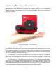
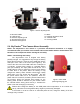
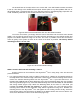
The dovetail base of the SkyTracker
TM
Pro comes with a 1/4"-3/8” thread converter, as shown
in FIG 9, It fits directly to the 3305A ball head quick release plate or any other platform with 1/4” or
3/8” threads screw. The alt-azi base fits to any standard camera or astrophotography tripod with 1/4"
or 3/8” threads by insert the 1/4”-3/8” thread converter into it, as needed.
Figure 9. Mount head dovetail base with 1/4"-3/8” thread converter
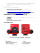
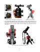
To use the alt-azi base, just simply slide the mount head base into the alt-azi base dovetail
saddle. You can slide the mount head in from either direction depending on your latitude position and
payload. The latitude adjustment range can be from -30° to 65°. If possible, choose the one with the
center of gravity of the system as close to the center of the base as possible. The factory default
mounting position is on 30° side.
Figure 10. Alt-azi base latitude settings
STEP 4. Install a ball head and mounting a camera
A DSLR camera can be mounted to the SkyTracker
TM
Pro in many ways. Here are two most
practical methods.
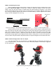
1. For a light payload (less than 1.2kg or 2.6lbs, including lens), a DSLR can be attached directly to
the SkyTracker
TM
Pro mount through a ball head. Loosen the two camera mounting block locks to
remove the Camera Mounting Block from the SkyTracker
TM
Pro. If your ball head has a 1/4"
threaded hole, fully thread the brass Mounting Screw into the Mounting Block with 1/4" threaded
side facing outside (Figure 11a). If the ball head mounting hole is 3/8” threaded, let 3/8” threaded
side facing outside (Figure 11b). Attach the Mounting Block to the base of a ball head (not
included) and make sure they are secured, as shown in Figure 11c. The ball head and the
mounting block should not be separated easily without significant turning force. Reattach the
mounting block to the SkyTracker
TM
Pro and tighten the two locking screws. Finally, attach the
quick release plate of the ball head to the bottom of the DSLR camera and secure it with the 1/4”
screw, then attached the camera to the ball head (Figure 12).