
Data Sheet


MCP2xxx Dual Channel Motor Controller Data Sheet
(c) 2015 Ion Motion Control. All Rights Reserved.
8
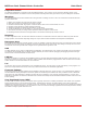
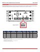
Wiring Basics
MCP must be wired correctly to ensure safe and reliable operation. The wiring diagram below illustrates one of several possible wiring
congurations. An external main power cut off solution should be incorporated for safety. Regeneration will occur if the motors are
moved when the system is off causing possible erratic behavior. Use a high current diode (D1) to create a return path to ground
when the unit is switched off. Use a precharge resistor (R1) to avoid high inrush currents and arcing. A precharge resistor (R1)
should be 1K, 2Watt for a 80VDC motor controller which will give a precharge time of about 15 seconds. A lower resistances can be
used with lower voltages to decrease the precharge time.
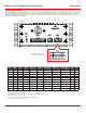
Wiring Closed Loop Mode
A wide range of sensors for closed loop modes are supported including absolute, quadrature, potentiometers and hall effect sensor.
The illustration below is an example of the wiring required for closed loop mode using quadrature encoders. Quadrature encoders are
directional. The internal hardware counter will increment and decrement based on the direction of spin. When wiring encoders it is
important they are wired to match the direction of the motor. If the encoder is wired in reverse it can cause a run away condition.
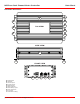
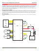
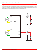
Wiring Diagram
Several wiring congurations are possible depending on the type of input or output being used. See the User Manual for additional
examples.
Encoder 1
A
B
GND
+5V
EN1 A
EN1 B
5VDC
GROUND
Encoder 2
A
B
GND
+5V
EN2 A
EN2 B
5VDC
GROUND
M1A
M1B
M2B
M2A
B-
B+
+
-
Battery
RX0
TX0
+5V
GROUND
MCP
Motor 1
Motor 2
UART TX
UART RX
5VDC
GROUND
MCU
R1
F1
D1