
Data Sheet


MCP2xxx Dual Channel Motor Controller Data Sheet
(c) 2015 Ion Motion Control. All Rights Reserved.
5
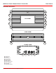
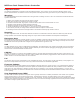
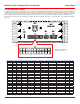
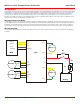
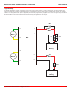
Control Interface (CTRL)
The MCP motor controllers use minature Molex connectors. The following tables list the pins and their functions. Most all pins are 15V
tolerant and output 3.3V for compatibility with processor such as Rasberry Pi and Arduino. CTRL pins are low side drivers at 40VDC,
1A per output. R/C pulse input, Analog and TTL can be generated from any microcontroller such as a Arduino or Rasberry Pi. The R/C
Pulse in pins can also be driven by any standard R/C radio receiver. There are several user congurable options depending on the
device used to control the motor contoller. To congure the motor controller connect it to a free USB port. Then install the IonMotion
PC utility.
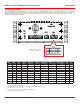
Pin PWR DIN DOUT ANALOG PULSE ENCODER UART TTL UART RS232 CAN I2C
1 DIN1 RX1 SDA
2 GND
3 DIN2 TX1 SCL
4 +5V
5 DIN3 AN1 P1
6 DIN4 P2 HALL1
7 DIN5 AN2 P3
8 DIN6 P4 HALL2
9 DIN7 AN3
10 DIN8 P5 HALL3
11 DIN9 AN4 P6
12 DIN10 P7
13 DIN11 AN5
14 DIN12 TX3
15 DIN13 AN6
16 DIN14 RX3
17 DIN15 AN7 P8
18 TX0 CANH
19 DIN16 P9
20 RX0 CANL
21 GND
22 LB+
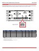
CTRL ENC
DRV
USB
ERR
STAT1
STAT2
MCP
IONMC.COM
1 3 5 7
11
13
15 17 19
21
2 4 6 8
12
14
16 18
20
22
10
9
Mating Connector Part
Number: 2-794617-2