
Data Sheet


MCP2xxx Dual Channel Motor Controller Data Sheet
(c) 2015 Ion Motion Control. All Rights Reserved.
10
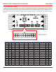
Contactors, Relays and Solenoids
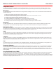
As a safety precaution an external power disconnect device should be used. A discconect such as a contactor, relay or solenoid
with the proper ratings for the planned load. The disconnect devices contacts should be rated for the total current output of both
motor channels combined. The disconnect device can be controlled by the DOUT pins or a simple manual switch. The DOUT pins
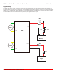
are designed to control inductive loads. They can be toggled by users programs. The wiring diagram below illustrates a basic wire
scheme using a relay as a disconnect for the main power. The DOUT controls the ground to the relay coil. The positive terminal of
the relay coil can be connected several ways depending on its rated voltage. The diagram below shows a 12VDC logic battery and
a 12VDC Rleay. If the relay coil is 5VDC the regulated user output (BEC) could be used instead. The main battery can also be the
power source provided a logic battery is present.
+
-
Battery
Motor 1
Motor 2
R1
F1
D1
M1A
M1B
M2B
M2A
B-
B+
MCP
F2
-
+
Logic
Battery
RY1
SW2
LB+
GND
LB+
DOUT