
Data Sheet


RoboClaw 2x30A Dual Channel Motor Controller Data Sheet
(c) 2016 Basicmicro. All Rights Reserved.
3
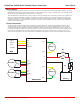
User Regulated Power Output
RoboClaw provides regulated power (BEC) for user devices. A high eciency switching regulator supplies 5VDC at up to
3 Amps. This voltage can be used to power external sensors, encoders, MCUs and other electronics. The regulated user
power is automatically current limited and thermally protected.
Main Battery
The peak operational input voltage depending on the model can be up to 34VDC, 60VDC or 80VDC. The models
maximum input voltage can not be exceeded. If the maximum voltage is exceed the motors will be disabled. Fully
charged batteries maximum voltage must be taken into account when in use. RoboClaw is a regenerative motor
controller. During regeneration, voltages can peak over the maximum rated voltage in which RoboClaw is designed to
handle these over voltage spikes by braking the motors.
Logic Battery
RoboClaw accepts a logic battery. The logic battery is also known as a backup battery. The user regulated power output
(BEC) is by default powered from the main battery, unless a logic battery is detected. The logic battery source is coupled
to the main battery through an on board automatic switch. If the main battery voltage drops below the logic battery
input level, the logic circuit and user regulated power output will be drawn from the logic battery.
Software
RoboClaw can be easily congured using the Motion Studio software tool. The Windows based application enables users
to quickly congure RoboClaw. The software can be used during run time to monitor and control several operational
parameters. Motion studio is available from the Basicmicro.com website. It can also be found in the Downloads section of
the Basicmicro website or listed under the Download tabs on the production page.
User Manual
This data sheet only covers model specic information and basic wiring. To properly setup and use RoboClaw refer to the
RoboClaw User Manual available for download from http://www.basicmicro.com.
Cooling
RoboClaw will generate heat. The maximum current ratings can only be achieved and maintained with adequate heat
dissipation. The motor controller should be mounted so that sucient airow is provided. Which will dissipate the heat
away from the motor controller during operation. Some models of RoboClaw include a built-in automatic cooling fan
controller, which can be used to help maintain continuous currents under extreme conditions.
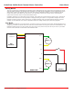
Emergency Stop
The motor controller should be wired using an external contactor, relay or high amperage mechanical switch to control
the main power input. A second power source should be used to power the logic section in situations where the main
power will be under heavy load. Voltage drops can occur from constant full load or high speed direction changes. Voltage
drop can cause logic brown outs if only a main battery is used without a logic battery.
USB
The motor controllers USB port should be used for conguration and debugging. The USB protocol is not designed for
electrically noisy environments. The USB port will likely disconnect and not automatically recover during operation
in electrically noisy environments. To recover from a dropped USB port, the motor controllers USB cable may require
being unplugged and re-plugged in. The TTL serial control should be the preferred method of control in electrically noisy
environments.
Firmware Updates
Firmware updates will be made available to add new features or resolve any technical issue. Before using RoboClaw
for the rst time it is recommended to update to the latest rmware. Download and install Motion Studio. Refer to the
RoboClaw User Manual or Application Notes for additional information on updating the RoboClaw rmware.