
Users Manual Part 4

IBA | 33-10 |
Clinical User’s Guide
Volume 1 - Treatment Session
|Part VI
- Using adaPT
deliver
in Standalone Mode Including One or More Beams into a Session
|
Snout Extension (cm): as defined in the beam, as the distance between
isocenter and the face of the block downstream the beam, or when there is
no block, the face of the range shifter or range compensator upstream the
beam (whether the beam definition comes from the DICOM plan created in
TPS or is set internally by the batch importer).
With the snout in the 10 cm position (i.e., the minimum position), a 10 cm
thick range compensator brings its edge at isocenter.
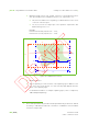
PPS:
X (cm): position along the X-axis.
Y (cm): position along the Y-axis.
Z (cm): position along the Z-axis.
Rotation (°): rotation of the PPS versus the beam line, expressed in degrees.
Pitch (°): a positive value indicates an increase, a negative value indicates a
decrease of the height of the treatment end of the couch, expressed in
degrees.
Roll (°): To tilt the couch top. A positive value for the roll angle is defined as
the direction that tilts the couch top counterclockwise when the PPS is in
the home position and viewed while facing the patient enclosure,
expressed in degrees.
Note: These coordinates are expressed in the IEC Table Top coordinate
system.
Dose:
Prescribed MU (MU): the number of MU as prescribed in the treatment
plan.
MU to be Delivered (MU): required MU count to be delivered to the
treatment site.
Expected irradiation time (sec): the irradiation is expected to take this long.
This value is used to perform a periodic check on the duration of the
irradiation.
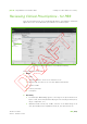
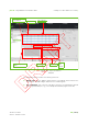
Displaying Layer Information
Note: Layer details are specific to the Uniform Scanning and Pencil Beam Scanning
treatment modes.
From the Information area, select the Layer tab and the clinical data on the layers of
the selected beam appear. This is the clinical data that is prescribed in the treatment
plan.