
Users Manual Part 4


Clinical User’s Guide
IBA | 30-17|
Volume 1 - Treatment Session
|Part IV
- Using
ada
PT
prescribe
Using QA Features of adaPT
prescribe
|
A PLD file contains a detail of the energy required for each layer and, for each layer,
the number of MUs and the position of each spot to be irradiated. From these data,
the system is able to calculate the setpoint to apply to the different system
components (such as the scanning magnets, accelerator, etc.) for each layer as well
as the threshold for all the checks that are done during the irradiation.
Note: Note that a PLD file only contains information about the spots/layers.
Information about the table/gantry/snout positions, beam name etc., should be input
manually in the beam information panel.
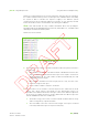
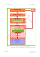
A PLD file looks as follows:
Figure 30-12. PLD File
(Typical)
The first line is the header: it contains information about the patient. The last 3
numbers are:
Red number: total of MUs to be delivered (also called beam meterset). The
amount of MUs that will be delivered in a spot is then equal to its meterset
weight multiplied by the total number of MUs and divided by the final
cumulative meterset weight.
Blue number: cumulative meterset weight, that is to say, the sum of the
meterset weight of each spot.
Green number: number of layers in the beam.
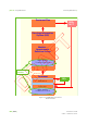
The second line is the ‘header’ of the first layer. The line starts with the word
‘Layer’, then ‘Spot1’ which is the spotID. For the same beam energy, It is
possible to have different beam line settings in order to have different spot sizes
at isocenter, the spotID tag is then used to differentiate the different spot size
that are available. The last four numbers are:
The beam energy a the nozzle exit without beam modifier (without range
shifter or ridge filter), expressed in MeV.
The red number is the sum of the meterset weight of the spots contained
in this layer and all the spots of the previous layer(s).