
Users Manual Part 2

IBA | 14-20 |
Clinical User’s Guide
Volume 1 - Treatment Session
|Part II
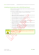
- Using Treatment Room Equipment Installing and Removing Accessories into/from the Accessory Drawer or PBS
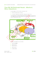
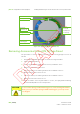
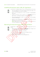
Figure 14-9. Type DN_XL Snout Components - continued
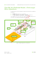
Seven LEDs are installed on the snout’s tray (from bottom to top), in two rows:
Rightmost row:
SNOUT SLOT 1.1
SNOUT SLOT 1.2
SNOUT SLOT 1.3
SNOUT SLOT 1.4
SNOUT SLOT 2
Leftmost row:
SNOUT INSERTED
SNOUT LOCKED
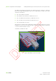
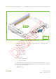
The LEDs turn ON (green light) when the respective switch detectors or the slot
position detector send a signal indicating that (each item corresponding to a LED in
the same order as the list above):
Rightmost row:
safety locks
(4 in total)
snout lock