
Users Manual Part 2


Clinical User’s Guide
IBA | 12-5|
Volume 1 - Treatment Session
|Part II
- Using Treatment Room Equipment Alignment Tools and Devices
|
systems a look-up-table is computed containing the deviations of the proton position
relative to the X-ray isocenter for different gantry angles and snout extensions. Such
deviations – whose typical values are of the order of 1mm and never exceed 5mm –
are obtained by positioning an ionization chamber detector or a radiographic film at
X-ray isocenter and measuring the relative distance to the center of the proton field.
The use of Proton Offset LUT ensures the patient is aligned with the isocenter where
the proton beam is delivered.
Relationship between Imaging equipment and
treatment geometries
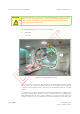
A geometrical calibration of the X-ray imaging system is required to compensate for
gantry deformations and lack of isocentricity. To this purpose, a correction is applied
at each gantry angle consisting of a flexmap with X-ray tube displacements, and
imager displacements and rotations. The geometrical calibration method uses a
phantom with radio-opaque markers which is positioned in the TR such that its
projection model is known if no geometrical deformations exist. The method then
computes the deviation of the measured X-ray projection with that of the model and
computes a geometrical correction which minimizes such deviation.
Typical values for tube and flat panel displacements are in the range of 2 to 20mm
while rotation components are as small as 0.3°. The same range of deformation is
observed in GTR configuration. However, values can differ quite significantly among
different sites and different rooms.
Alignment
When an acceptable alignment is reached:
1. Select the Treatment beam.
2. Look at the X-ray image again from the adaPTinsight workstation: the outline is
on the image.
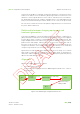
Figure 12-2. adaPTinsight Integration With the TCS
PPS
TCS
Dicom
adaPTinsight
apply automatically
(or manually)
implement using
hand pendant
Dicom
server
TPS