
Users Manual Part 2


IBA | 12-4 |
Clinical User’s Guide
Volume 1 - Treatment Session
|Part II
- Using Treatment Room Equipment Alignment Tools and Devices
|
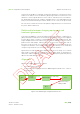
The GTR imaging geometry consists of the following:
1 portal axis
1 ortho axis
Figure 12-1. GTR Imaging Geometry
The isocenter which is used to align the patient in the TR changes position during
gantry rotation due to gantry deformation and nozzle deformation. These two effects
need to be compensated in order to have the proton beam delivered at the intended
location.
To compensate for gantry deformation a geometrical calibration is computed thus
defining the X-ray isocenter. The proton LUT is not required in systems equipped with
PBS dedicated nozzle as in this case the direction of the proton beam is tuned to
match the X-ray isocenter. To compensate for nozzle deformations in universal nozzle
Important If the administration of your center has established any such procedure,
make sure that a regular backup is taken of the adaPTinsight log files
containing the information on the dose delivered to each patient by
means of X-rays or fluoroscopy.
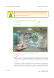
Orthogonal
flat panel arm
Portal flat panel
arm
Laser
Nozzle
Snout
Drawer
PPS
Caterpillar
Squirrel cage
Back wall panel
Angular indicator
Treatment
software
screen