
Users Manual Part 1


Clinical User’s Guide
IBA | 6-3|
Volume 1 - Treatment Session
|Part II
- Using Treatment Room Equipment Elementary Notions on Patient Positioning
|
Supported Coordinate Systems
A coordinate system is a system that defines the position of a point in space. A
coordinate system is defined by its origin and axes X, Y, and Z. All coordinate systems
used by the Treatment Control System (TRCS) are Cartesian right-handed (axis X is
the thumb, Y is the index, and Z is the middle finger).
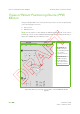
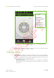
Positioning and alignment data are stored in the PTS database according to the
IEC61217 standard. All PPDs’ positions are represented according to IEC61217
standard both on screen and in the database. The IEC61217 defines a unique way to
display the table, snout and gantry positions.
Note: Imager and Focus coordinate systems defined in IEC61217 are not used.
Within the TRCS the following IEC 61217 compliant Coordinate Systems are used:
Fixed Reference System (FRS): for detailed information, refer to section "IEC
Fixed Reference System (f)" on page 6-3.
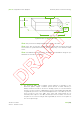
Gantry Coordinate System (GCS): for detailed information, refer to section
"IEC Fixed Coordinate System" on page 6-4.
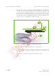
Table Top Coordinate System (TTCS): for detailed information, refer to section
"IEC Table Top Coordinate System (t)" on page 6-5.
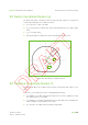
IEC Fixed Reference System (f)
The IEC61217 Fixed Reference System (FRS) is defined on the basis of the radiation
beam axis, the gantry axis and the isocenter. In the GTR there is a rotating radiation
beam axis that orthogonally crosses a fixed gantry axis through a common isocenter.
The FRS is defined as follows:
the origin is at isocenter
X
f
is aligned with the beam axis and directed towards the beam source when
the gantry is at 90°
1
Y
f
is aligned with the gantry axis and directed to the left of a viewer facing the
beam source when the gantry is at 90°
2
Z
f
is vertical and directed upwards
1. By convention, the gantry angle is 90° when the radiation beam axis is horizon-
tal, at 90° from Z
f
and directed in the opposite direction of X
f
.
2. When the radiation beam axis is horizontal, Y
f
is the horizontal axis passing
through the FRS origin, and orthogonal to the beam axis.