
Users Manual
ISM14585-EVB User’s Manual
DOC-DS-14585-EVB-201911-3.6
Confidential Inventek Systems
Page 17
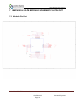
8 ISM14585 MODULE PCB INTERNAL ANTENNA LAYOUT
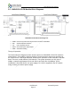
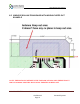
8.1 Configuration Example 1:
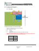
8.1.1 Top view
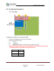
Configuration Example 1 recommended design:
• Position the ISM14585 module near the PCB edge.
• Route the keep out for 3mm
• A: 3mm typ.
• B: >= 3mm typ.
• C: KEEP OUT extends the entire width of the module (6mm typ)
•
NOTE: There should be NO Copper in the KEEP OUT area for all Layers except for the
internal RF Antenna Trace (Please reference Section 9.0).
Parameter
Unit: mm
A
3.0 (typ.)
B
3.0 (typ.)
C
6.0 (typ)