ISM14585-EVB User’s Manual ISM14585-L35-P8-EVB BLE 5.0 SiP Evaluation Board User’s Manual 5.0 BLE + Cortex M0 + PMU + PA + 8Mb Flash DOC-DS-14585-EVB-201911-3.
ISM14585-EVB User’s Manual Table of Contents 1 PART NUMBER DETAIL DESCRIPTION .................................................................................. 3 1.1 Ordering Information ...................................................................................................... 3 1.2 Ordering Information Configuration............................................................................... 3 2 OVERVIEW .....................................................................................
ISM14585-EVB User’s Manual 1 PART NUMBER DETAIL DESCRIPTION 1.1 Ordering Information Device ISM14585-L35-P8-EVB Internal Antenna Evaluation Board ISM14585-L35-P8-EVB-W w.fl External Antenna Evaluation Board B24P-W w.fl Certified External Antenna Note: • • Description BLE 5.0 + Cortex M0 Module with integrated PMU, PA, 8Mb of Flash and internal antenna EVB (Evaluation Board) BLE 5.0 + Cortex M0 Module with integrated PMU, PA, 8Mb of Flash and w.fl external antenna EVB (Evaluation Board) Certified w.
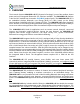
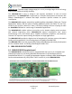
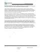
ISM14585-EVB User’s Manual 2 OVERVIEW The Inventek Systems ISM14585-L35 SiP (System in Package), is one of the smallest, lowest power and most integrated Bluetooth® 5.0 solutions available. The ISM14585-L35 platform is the first BLE module from Inventek's FLEXiBLE product family. The ISM14585-L35 SiP is an embedded wireless Bluetooth Low Energy (BLE) IoT radio, based on the Dialog Semiconductor DA14585 radio SoC (System on Chip).
ISM14585-EVB User’s Manual additional cost. The wide supply voltage range (0.9 –3.6 V) covering a larger choice of energy sources also enables full design flexibility. The ISM14585-L35 is easy to design-in and supports standalone as well as hosted applications. The ISM14585-L35 is supported by a complete development environment with Dialog’s SmartSnippets™ software that helps customers optimize software for power consumption.
ISM14585-EVB User’s Manual 3.2 Dialog’s DA14585-00ATDEVKT-P Development Kit – Pro Motherboard EVK and SDK SmartSnippets Studio The Dialog’s SDK SmartSnippets Studio includes all of the support required for the tool chain, build system, the BLE driver and the software stack together with example applications. The SDK also runs on Windows. The ISM14585-EVB provides a platform for the design and development of applications to run on the ISM14585-L35-P8 SiP Module. 3.
ISM14585-EVB User’s Manual 3.4 Key Benefits • • • Lowest power consumption Smallest system size Lowest system cost 3.5 Limitations Inventek Systems products are not authorized for use in safety-critical applications (such as life support) where a failure of the Inventek Systems product would reasonably be expected to cause severe personal injury or death. 3.
ISM14585-EVB User’s Manual Class 2 permissive changes must be performed under Inventek’s grant, and therefore must be done in cooperation with Inventek. In addition to this document, Inventek recommends verifying the schematic board design with Inventek Engineering once the schematic is complete for further review and validation. If it is desired to add a connector or U.
ISM14585-EVB User’s Manual Manufacturer Inventek Inventek Type of Antenna Integrated Trace Model N/A B24P-W Gain dBi -1 3.2 Type of Connector embedded w.fl This device complies with part 15 of the FCC Rules. Operation is subject to the following two conditions: (1) This device may not cause harmful interference (2) This device must accept any interference received, including interference that may cause undesired operation.
ISM14585-EVB User’s Manual L’opѐ ration est soumise aux deux conditions suivantes: (1) cet appareil ne peut pas provoquer d’interfѐ rences et (2) cet apparial doit accepter toute interfѐ rence, y compris les interfѐ rences qui peuvent causer un mauvis fonctionment de l’appareil. Under Industry Canada regulations, this radio transmitter may only operate using an antenna of a type and maximum (or lesser) gain approved for the transmitter by Industry Canada.
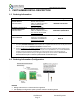
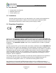
ISM14585-EVB User’s Manual 4 Dialog SDK and Tool Chain Initialization Instructions 4.1 Go to the Dialog “Get Support” link : 4.1.1 https://www.dialog-semiconductor.com/bluetooth-low-energy 4.1.2 Scroll down to SmartBond™ Product Portfolio & select DA14585 4.2 Scroll down to “Development Tools” 4.2.1 Download the most recent SmartSnippets Studio for you OS 4.2.2 Download the most recent SmartSnippets Studio User’s Manual 4.3 Scroll to the “SDK” section 4.3.
ISM14585-EVB User’s Manual 5 ISM14585-L35-P8 RADIO & MODULE BLOCK DIAGRAM 5.1 ISM14585-L35-P8 Radio Block Diagram ISM14585-L35-P8 Radio Block Diagram (Reference the ISM14585-L35-P8 Data Sheet for details) DOC-DS-14585-EVB-201911-3.
ISM14585-EVB User’s Manual 5.2 ISM14585-L35-P8 Module Block Diagrams ISM14585-L35-P8 Module Block Diagrams • • • • • UART SPI I2C GPIO SWD Universal synchronous/asynchronous receiver transmitters Serial Peripheral Interface Inter-Integrated Circuit General-purpose input/output Serial Wire Debug Theory of Operation: The functional block diagram for each antenna option for ISM14585-L35-P8 RF module is shown above. This module is a direct sequence spread spectrum transceiver operating in the 2.
ISM14585-EVB User’s Manual 6 ANTENNA CONFIGURATION OPTIONS 6.1 Integrated Antenna DOC-DS-14585-EVB-201911-3.
ISM14585-EVB User’s Manual 6.2 External w.fl Antenna DOC-DS-14585-EVB-201911-3.
ISM14585-EVB User’s Manual 7 ISM14585-L35-P8 MODULE SCHEMATIC & PIN OUT 7.1 Module Pin Out DOC-DS-14585-EVB-201911-3.
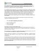
ISM14585-EVB User’s Manual 8 ISM14585 MODULE PCB INTERNAL ANTENNA LAYOUT 8.1 Configuration Example 1: 8.1.1 Top view Configuration Example 1 recommended design: • • • • • Position the ISM14585 module near the PCB edge. Route the keep out for 3mm A: 3mm typ. B: >= 3mm typ. C: KEEP OUT extends the entire width of the module (6mm typ) • NOTE: There should be NO Copper in the KEEP OUT area for all Layers except for the internal RF Antenna Trace (Please reference Section 9.0). Parameter A B C Unit: mm 3.
ISM14585-EVB User’s Manual 8.2 Configuration Example 2: 8.2.1 Top View Configuration Example 2 recommended design: • • • • • • Position the ISM14585 module near the PCB edge. Route the keep out for 3mm A: 3mm typ. B: >= 3mm typ. C: KEEP OUT extends the entire width of the module (6mm typ) NOTE: There should be NO Copper in the KEEP OUT area for all Layers except for the internal RF Antenna Trace (Please reference Section 9.0). Parameter A B C Unit: mm 3.0 (typ.) 3.0 (typ.) 6.
ISM14585-EVB User’s Manual 8.3 ISM14585 EVALUATION BOARD WITH MODULE KEEP OUT EXAMPLE NOTE: THE DISTANCE BETWEEN THE TOP ROW OF PADS AND THE KEEP OUT AREA IS 0.240mm AND THIS ARE IS ALSO TREATED AS KEEP OUT DOC-DS-14585-EVB-201911-3.
ISM14585-EVB User’s Manual 8.4 ISM14585 RF OUTPUT TO INTERNAL ANT. REQUIRED RF TRACE LAYOUT DOC-DS-14585-EVB-201911-3.
ISM14585-EVB User’s Manual 9 ISM14585 MODULE EXTERNAL ANTENNA LAYOUT 9.1 W.FL EXTERNAL ANTENNA REQUIRED LAYOUT DOC-DS-14585-EVB-201911-3.
ISM14585-EVB User’s Manual 10 REVISION CONTROL Document: ISM14585-EVB External Release ISM14585 Evaluation Board DOC-DS-14585-201911-3.6 Date Author Revision Comment 5/05/2018 7/04/2019 9/17/2019 AS AS AS 1.0 2.0 2.5 10/4/19 AS 3.0 11/1/19 AS 3.1 11/19/19 AS 3.5 7/9/20 AS 3.6 Preliminary Schematics Update Antenna Keep Out and Trace Layout Updated w.