
User's Manual

INSTALLATION INSTRUCTIONS
It is recommended that installation be performed by a qualified installer.
Location
To ensure proper operation, the thermostat should be mounted on an
inside wall in a frequently occupied area of the building. In addition, its
position must be at least 18" (46cm) from any outside wall, and approx-
imately 5' (1.5m) above the floor in a location with freely circulating air
of an average temperature. You should avoid the following locations:
- behind doors or in corners where freely circulating air is unavailable;
- where direct sunlight or radiant heat from appliances might affect
control operation;
- on an outside wall;
- adjacent to, or in line with, conditioned air discharge grilles, stair-
wells, or outside doors;
- where its operation may be affected by steam or water pipes or
warm air stacks in an adjacent partition space, or by an area behind
the thermostat which is not climate controlled;
- where its operation will be affected by the supply air of an adjacent
climate control HVAC device;
- near sources of electrical interference such as arcing relay contacts.
TERMINAL DESIGNATIONS
CONVENTIONAL
Y2 . . . . . . .Compressor is energized for 2
nd
stage cooling
W1 . . . . . .Energizes for 1
st
stage heating
Y1 . . . . . . .Compressor energized for 1
st
stage cooling
W2 . . . . . .Energizes for 1
st
stage heating
HEAT PUMP
Y2 . . . . . . .Compressor is energized for 2
nd
stage heating or cooling if
multistage is selected
W1 . . . . . .Auxiliary heat is energized as back-up or emergency heat
Y1 . . . . . . .Compressor energized with a call for heating or cooling
O . . . . . . .Energizes the reversing valve continuously in cool mode
B . . . . . . . .Energizes the reversing valve continuously in heat mode
CONVENTIONAL OR HEAT PUMP
G . . . . . . .Fan operates with a call for heating or cooling or by pressing
the FAN button.
R . . . . . . . .Power from equipment
24V . . . . . .24 VAC hot and common to power the thermostat
24(c)
RS2 . . . . .Use to connect up to 6 (SL-IDS) indoor and/or 1
RS1 (SL-ODT) outdoor remote sensor/s.
RS+V When connected the thermostat will automatically use the
SL-IDS temperature sensor and not its own. Refer to the
instructions included with the sensor.
FAULT . . .Equipment Fault input. Connect through dry relay contact to
GP+V to signal equipment fault. Causes wrench icon to be
displayed on LCD and locks out all heat-pump stages (heat-
pump operation selected via DIP switch) when there is a call
for heat.
GPI1 . . . . .General purpose inputs. Connect through dry contact relay
GPI2 to GP+V
GP+V
X1 . . . . . . .Communication line
X2 . . . . . . .X1 return, connected to 24V(c)
SPECIFICATIONS
Rated Voltage . . . . . . . .20-30 VAC, 24 nominal
Rated A.C. 0.050 Amps to 0.75 Amps continuous
Current . . . . . . . . . . . . . .per output with surges to 3 Amps Max.
Rated D.C. 0 Amps to 0.75 Amps continuous
Current . . . . . . . . . . . . . .per output with surges to 3 Amps Max.
Default Control . . . . . . .Heating: 40° to 88°F in 1° Steps
Range 6° to 30°C in 1° Steps
Cooling: 60° to 95°F in 1° Steps
16° to 33°C in 1° Steps
Maximum . . . . . . . . . . . .Heating & Cooling: 40° to 95°F in 1° Steps
Programmable 6° to 33°C in 1° Steps
Control Range
Thermostat . . . . . . . . . .28° to 124°F or 0° to 48°C
Measurement Range
Minimum . . . . . . . . . . . .(between heating and cooling)
Deadband 2°F or 1°C
NOTE: This thermostat contains electronic circuitry replacing the
conventional mechanical anticipator.
DSL-600SC-HCS 111-315
VACANT
(Occ4)
USER DEFINED
(USr1-USr4)
1
2
3
4
HOME
(Occ1)
AWAY
(Occ2)
SLEEP
(Occ3)
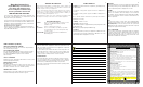
OCCUPANCY MODES
DESCRIPTION OF ICONS
WIRING DIAGRAM
Note: If the 24V(c) is not available from the equipment the jumper may be
removed and a separate 24V transformer must be used to power the thermostat.
This thermostat may be used with 24 Volt DC. The negative side of the DC
supply must be wired to the 24V (c) terminal.
9
10
11
12
16
14
13
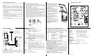
DSL-600SC-HCS
Alarm LED (Left)
Auxiliary Heat LED
(Center)
Economy LED (Right)
GPI1
FAULT
GPI2
GP+V
RS2
RS1
RS+V
X2
X1
Y2
W1
Y1
G
R
24v
24v(c)
O/W2
B
Temperature Sensor
Display
New
R/24v Jumper replaced
with a connector (shunt).
Remove if thermostat power
is not supplied by equipment.
Removing the Thermostat from the Subbase
1. Insert a flat blade screwdriver or coin 1/8" into the slot located in the
bottom center of the thermostat case and twist 1/4 turn. When you feel
or hear a click, grasp the case from the bottom two corners and sepa-
rate from the subbase.
2. Swing the thermostat out from the bottom.
3. Lift the thermostat up and off the subbase.
4. Place the rectangular opening in the subbase over the equipment con-
trol wires protruding from the wall and, using the subbase as a tem-
plate, mark the location of the two mounting holes (exact vertical
mounting is necessary only for appearance).
5. Use the supplied anchors and screws for mounting on drywall or plas-
ter; drill two 3/16" (5mm) diameter holes at the marked locations; use a
hammer to tap the nylon anchors in flush to the wall surface and fasten
subbase using the supplied screws. (Do not overtighten!)
6. Connect the wires from your system to the thermostat terminals.
Carefully dress the wires so that any excess is pushed back into the
wall cavity or junction box. Ensure that the wires are flush to the plastic
subbase. The access hole should be sealed or stuffed to prevent drafts
from affecting the thermostat.
Replacing the Thermostat on Subbase
1. Position the thermostat on the hinged
tabs at the top of the subbase.
2. Gently swing the thermostat down
and press on the bottom center until
it snaps into place.
Thermostat Cover Lock
Insert the plastic lock piece into the bot-
tom of the mounted base. The ends of
the lock piece fit snugly under the lock
pins extending from the bottom of the
mounted base. The tab in the middle of
the lock piece extends down from the
base.
To release the locking mechanism,
press the lock piece up and into the
base while gently prying open.
Thermistor Mounting Instructions
When placing the front cover on the
thermostat ensure the thermistor is not
bent or misaligned.
Ensure that the thermistor does not
touch the thermostat case. The thermis-
tor should be placed horizontal to the
wall. Ensure the thermistor is not
pushed upward into the case.
The thermistor should be aligned so it is
visible between the ribs on the bottom
of the subbase.
DIP SWITCH OPTIONS AND FUNCTIONS
Positioning the DIP switches in either the ON or OFF position enables
you to choose between two different options. The DIP switches are
located on the interior of your thermostat and may be accessed by fol-
lowing the procedure for removing the thermostat from the subbase.
The following list describes your DIP switch options.
1. Not Used This switch must remain in the OFF position.
2. Not Used This switch must remain in the OFF position.
3. Conventional or Heat Pump Set to OFF position for conventional sys-
tems, or ON for heat pump systems.
4. 2 Minute or 4 Minute On/Off Times This option allows you to run the
equipment for either a 2 or 4 minute off and on time.
5.Plenum Fan (Conventional) In the OFF position, the fan comes on
immediately with a call for heat. In the ON position, the fan is controlled by
the equipment (plenum switch control).
5. Add-On Heat Pump (Heat Pump) In the OFF (normal) position, the
thermostat will allow the compressor and the auxiliary heat to be on at the
same time. In the ON (add-on) position, the compressor is turned off with
a call for auxiliary heat.
6. Single or Multi-stage Set to OFF for systems with no more than one
stage of cooling AND no more than one stage of heating (excluding the
auxiliary heat stage in heat pump applications), or ON for systems with
two stages of cooling OR two stages of heating (excluding the auxiliary
heat stage in heat pump applications).
7. Not Used This switch must remain in the OFF position.
8. Not Used This switch must remain in the OFF position.
DIP Switch
DIP Switch OFF
DIP Switch ON
1
2
3
4
5
6
7
8
Not used (OFF position)
Not used (OFF position)
Conventional
4 minute minimum ON/OFF
Normal
Single stage
Not used (OFF position)
Not used (OFF position)
Not used
Not used
Heat Pump
2 minute minimum ON/OFF
Plenum Fan (conventional)
Add-on (heat pump)
Multi-stage
Not used
Not used
15