
User's Manual


4-antenna port1;
5-antenna port2;
Note: Every antenna port must connect with an antenna or 50 ohm load
before the reader power up. otherwise the reader will be damaged.
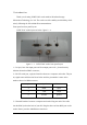
XCRF-502C reader rear panel figure 2-2:
figure 2-2 XCRF-502C reader rear panel figure 2-2
1-AC INLET;
2-Power Indicator, green-colour light, green light indicates that the reader power
on;
3-Power Amplifier Indicator, red-colour light, Red light indicates the reader is
transmitting Radio frequency power from RF port;
4-Link Indicator ,green light, green light indicates that the Reader has linked with
Computer from Ethernet network port;
5-Communication, blue light, ,blue lighting indicates that the reader is
communicating with computer ;
6-Receive light, green lighting indicates that the reader is communicating with the
tag;
7-power switch;