
User's Guide


LSP3A Clear User’s Guide
It is only for internal use and shall not be spread without permission
32
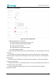
5.5.3.5 GPIO
Figure 5.15: GPIO
GPIO1 has 3 types:
GPIO
Input Trigger
Output Trigger
GPIO2 has 2 types:
GPIO
Output Trigger
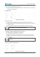
Checking GPIO level
The two GPIO available to user can be monitored:
Display shows “High” when voltage level is above 2 Volt.
Display shows “Low” when voltage level is below 1 Volt
Clicking with the mouse on GPIO text field, the Level value toggles between High & Low.
The effect will depend on the actual GPIO settings on GPIO module.
GPIO1 can be set as an Input Trigger for RF powering off/on as well as an Output for driving
an External Alarm Device.
GPIO2 can only be used as an Output for driving an External Alarm Device.
Configuring General Purpose Input/Output
When needed, port #1(GPIO1) can be used as an input to remotely switch the RF Field on
and off. This is useful to limit the HF field generation to a strict minimum, i.e. whenever a person is
about to enter the detection passageway crossing a light barrier placed ahead of the pedestal and
keep it on for a fixed duration or whenever the person is exiting the RFID detection area using a
second light barrier beam crossing detector.
Refer to Figure 5.17 for the pin layout to wire the Input and output signals.
In section GPIO1, select one of the available options:
GPIO: Port has no predefined function; it can be driven remotely by Host PC via
API.
Input Trigger: when wired signal matches the Active Level Setting(“Low” or “High”)
the Radio Frequency Field will be turned On, Theft detection becoming active.
Output Trigger: when Theft is detected(EAS or AFI signal setting the alarm), the Port
Signal level matches the Active Level Setting(“Low” or “High”). The output voltage