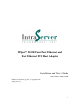
ITIpci 5232E Four Port Ethernet and Fast Ethernet PCI Host Adapter Installation and User’s Guide Order Number 9806-5232M IntraServer Technology, Inc., Copyright 1998 quad_enet.
Copyright 1998 First Printing, June 1998 Copyright Copyright 1998 IntraServer Technology, Inc. No part of this manual may be reproduced in any form, mechanical or electronic without the prior written consent of IntraServer Technology, Inc. Seven October Hill Road, Holliston, MA 01746. Trademarks The following are trademarks of IntraServer Technology, Inc. ITIpci, ClusterReady, and the IntraServer logo. All other trademarks are the property of their respective holders and acknowledged.
Class B Device Certification Statements Federal Communications Commission Radio Frequency Interference Statement This equipment has been tested and found to comply with the limits for a Class B digital device, pursuant to Part 15 of the FCC rules. These limits are designed to provide reasonable protection against a harmful interference in residential installations.
Introduction........................................................................................................................ 6 ITI-5232E Four Port Ethernet and FAST Ethernet Kit Contents ........................................ 7 Connectors and Indicator LEDs ............................................................................................... 8 Hardware Installation........................................................................................................
Tables Table 1 ITI-5232E Adapter Models ________________________________________________________7 Table 2 Connections and Indicator LEDs ___________________________________________________8 Table 3 Contents of Software Distribution Floppy ___________________________________________11 Table 4 Digital UNIX and OpenVMS SRM Console Media Selection _____________________________28 Table 5 8-Pin MJ Connector Pin Assignments_______________________________________________30 Table 6 Adapter to Network Hub Wiring ____
Introduction IntraServer’s Four Port ITI-5232E provides four FAST (10/100Mb/sec) channels from a single PCI host slot, providing the maximum network integration for high performance network server needs. Each of four ports is capable of running FAST, FAST Full Duplex, or 10Mb/sec for configuration flexibility, allowing a single card to communicate with FAST or Standard Ethernet systems simultaneously.
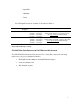
- OpenVMS - MS/DOS - Linux Two ITI-5232E models are available, as described in Table 1.
Connectors and Indicator LEDs The ITI-5232E provides four 8-pin Modular Jack (MJ) connectors for connection with your network. Each of these four ports supports either Twisted Pair Category 3 or 5 cable for 10Mb/s connections, or Category 5 cable for 100Mb/sec operation. Figure 1 shows the ITI-5232E Adapter connectors and indicator LEDs.
Hardware Installation This chapter describes how to install the ITI-5232E adapter in your PCI based bus master compatible computer, and how to connect it to your network. The ITI-5232E host adapter is Plug and Play on the host systems PCI bus, and no configuration of the adapter hardware is necessary. System Requirements Before you begin the installation procedure, you will need: • An available PCI bus master expansion slot • A system that is compatible with the PCI Specification, Version 2.
5. Locate a free PCI expansion slot (small white connector on the system’s motherboard) and remove the screw and metal bracket for the selected slot. Be certain not to install the adapter in an ISA or EISA slot, which are longer than the PCI slots 6. Install the adapter in the selected slot. The module should fit without forcing, and should line up with the I/O bulkhead. Be certain that the adapter is fully seated in the slot 7. Replace the retaining screw removed in step 5 8.
Network Device Driver Installation Instructions Windows NT The ITI-5232E Four Port Ethernet and Fast Ethernet adapter uses the industry leading Fast Network Engine, Digital’s DC21143 PCI MAC. Digital’s DC21X4.SYS mini-port driver is used to support the four Ethernet channels on the card. Contents of the driver kit Your ITI-5232E kit includes a floppy disk, which contains the Windows NT and Windows 95 drivers.
Installing the ITI-5232E (DC21X4 Driver) on Windows NT: Follow the procedure below to install the NT driver on your Intel or Alpha based system. The choices you are given may vary slightly from these examples based on your machine’s current network configuration and options. See your system administrator for any additional information. Note: Digital’s Alpha systems use a dynamic link library file (DLL) called a hardware abstraction layer (HAL).
If a dialog box asks you "Do you want to install NT Networking?" select YES and continue. Place the Windows NT installation media the CD-ROM reader, and complete the Windows NT network installation. Consult Windows NT documentation if you are unfamiliar with this process. Follow the on-screen prompts until you are prompted for a Network Adapter Type. 3. From the “Network” dialog, select the Adapters tab, then select Add. 4.
5. Insert the ITI-5232E driver diskette in your floppy drive and select OK.
6. From the “Select OEM Option” dialogue, Select “IntraServer ITI5232E Four Port 10/100 Mbps Ethernet” adapter, and select OK. 7. A “Connection Type” dialog box will allow you to select the connection type appropriate for your network configuration. The default connection type is AutoSense, which should be correct for most network connections. 8. Should you need to change the media connection type, be certain to select the correct connection type for your network.
9. Upon completion, the selected adapter port(s) is (are) added to the Installed Adapter Cards list in the Network Setting box (the number prefixing the adapter is the adapter port number). 10. Select OK to complete the Network Setting initialization. Based on the protocols you are running, one, or more dialog boxes may appear. See your network administrator for appropriate settings for your network for each of the dialog boxes. A typical dialog (TCP/IP) shown for example.
11. Shutdown and reboot the system.
Windows 95 Installation for PCI systems The following step should be taken in order to use the IntraServer Technology, Inc. ITI5232E Four Port Fast Ethernet 10/100 adapter in a system running Windows 95: 1. Power the machine down, unplug the AC power line, and remove the access cover. 2. Install the ITI5232 into an unused PCI slot. Attach the network cable(s) from the card to your existing network device. 3. Replace the access cover of your machine. 4. Replace the AC power line, and boot Windows 95. 5.
12. Windows ’95 may prompt you to insert the distribution media disk(s) to be installed at this time. 13. Some files will be copied from your distribution media disk(s) and some from the OEM distribution floppy disk. 14. If Windows prompts you for a file location of the distribution files, select the default location A:\ and select OK.
15. When all necessary files have been copied to your system, select Finish from the “Add New Hardware Wizard” dialogue. 16. The preceding steps will be repeated for EACH of the four ports detected by Windows ’95. You will need to repeat the above procedures until each of the four ports have been added to your configuration. 17. Each port on the ITI-5232E Four Port Network adapter will be given an entry in the adapter list in the “Network” dialogue. 18.
19. The ITI-5232E is capable of full AutoSense, which should allow plug and play operation with your network. Should the need arise to specify the physical media, select the “Advanced” tab, then select Connection Type, and select the connection type that matches your network. 20. Select OK. Based on the network protocols running on your system, one or more dialogue boxes may appear. See your network administrator for the network settings for this machine.
21. When prompted, allow the machine to restart, to allow the new network settings to become active.
NetWare The Novell Netware driver, DC21x4 is used with both Netware 3.1x and Netware 4.x servers. Netware 3.x Server Driver 1. Prepare the hard drives of your server according to the instructions in your Netware 3.1x documentation. 2. While the server is down, insert the IntraServer Setup diskette into your server’s A drive. 3. Copy the contents of a:\netware\311 or a:\netware\312 to the disk from which you boot Netware 3.1x 4. Type SERVER at the DOS prompt press Enter to boot the Netware 3.1x Server. 5.
9. Enter information as prompted. You may modify the adapter’s default configuration by changing its parameters when prompted. The default settings provide best results in most cases.
Linux For information regarding drivers, installation, and support for Linux please visit our World Wide Web site at http://intraserver.com/support/faq.
Digital UNIX Drivers for the ITI-5232E are on the Digital UNIX distribution kit beginning with Version 4.0D. Digital UNIX will identify the ITI-5232E as four 21140 based Ethernet controllers. Once the hardware is installed in your system, boot the system using genvmunix, in the following manner: >>>boot –file genvmunix This will cause Digital UNIX to scan all hardware devices in the system, and identify the ITI-5232E . Four 21140 based Ethernet adapters will be identified.
Digital OpenVMS Drivers for the ITI-5232E are on the Digital OpenVMS distribution kit beginning with Version 7.1. Digital OpenVMS will identify the ITI-5232E as four 21140 based adapters. Follow the documentation for the network software you will be running on the adapter for specific configuration information. Note: Digital OpenVMS relies on the settings for media type and speed set by the SRM console. See Appendix A for more information.
Appendix A Digital’s SRM Console Settings When the ITI-5232E is being used in a Digital Alpha platform running OpenVMS or Digital UNIX, the SRM console is used to set the port speed, media (cable) type and boot protocols, and can also be used to test the module. After powering your system up, and before booting your operating system, the system will stop at the SRM console prompt. On a uni-processor machine, the SRM prompt is “>>>” and on the primary processor of a multi-processor machine, is “P0>>>”.
For example, to set the media type and speed to FAST Twisted Pair, enter the command: >>>set ewa0_mode FAST If you will be remote booting via the Ethernet, you must also set the boot protocol to match that of the boot node. Typically OpenVMS uses MOP protocol and UNIX uses BOOTP. For example to set a port to MOP (VMS) use: >>>set ewa0_protocol MOP Note: Port 0 will be the lowest controller letter found by the SRM console, “A” if there are no other Ethernet ports in the system.
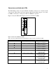
Appendix B Connector Pin Assignments Each of the Four 8-pin MJ connectors for 10/100 Mb/sec are wired as shown in Figure 2: 12345678 Figure 2 8-Pin MJ Connector (Front) With the connection pins assigned as shown in Table 5: Pin Number 1 2 3 4 5 6 7 8 Signal Name Transmit + TX (+) Transmit TX (-) Receive + RX (+) No Connection NC No Connection NC Receive RX (-) No Connection NC No Connection NC Table 5 8-Pin MJ Connector Pin Assignments Connection from the ITI-5232 adapter to a network hub must be made
Table 6 Adapter to Network Hub Wiring Connection from the ITI-5232E adapter to another network adapter (point to point) must be made as shown in Table 7: Crossover TX (+) TX (-) RX (+) RX (-) Adapter 1 Pin 1 2 3 4 5 6 7 8 ÇÈ ÇÈ ÇÈ ÇÈ Adapter 2 Pin 3 6 1 4 5 2 7 8 RX (+) RX (-) TX (+) TX (-) Table 7 Adapter to Adapter (point to point) Wiring Cabling Requirements In order for your network to operate properly, you must use a category of network cabling that is appropriate for the data rate of the cha
Appendix C: Troubleshooting Windows NT Version 4.0 and 3.51 The most common problem encountered on Windows NT for Ethernet devices is a mismatch of the port’s speed and media settings to those in use on the network. The most simple check of correct cabling is to observe the status lights on the handle of the card. Once the card is installed in the system, the software is installed, and the module is wired to your network hub, the LINK light should be illuminated.
DC21X4_ERRMSG_TXM_JABBER_TIMEOUT 0x07 Table 8 DC21X4 NT driver error codes Driver initialization errors: NDIS_ERROR_CODE_UNSUPPORTED_CONFIGURATION DC21X4_ERRMSG_REGISTRY The AdapterType Registry’s key is missing or its value is unsupported by the adapter board NDIS_ERROR_CODE_ADAPTER_NOT_FOUND No board matching the AdapterCFID Registry’s key value was found plugged into the PCI bus or in the slot specified in the Registry NDIS_ERROR_CODE_OUT_OF_RESOURCES DC21X4_ERRMSG_ALLOC_MEMORY Not enough memory to al
NDIS_ERROR_CODE_HARDWARE_FAILURE DC21X4_ERRMSG_SYSTEM_ERROR System_Error interrupt (bus parity error) NDIS_ERROR_CODE_HARDWARE_FAILURE DC21X4_ERRMSG_TXM_JABBER_TIMEOUT Transmit Jabber timer expired Windows 95 If the adapter is not detected by Windows 95 after installing the adapter, and rebooting Windows 95, check the following: 1. Double click on My Computer/Control Panel/System to display the System Properties Page. 2.
Appendix D: Adapter Specifications ITI-5232E Four Port 10/100 Ethernet PCI adapter Bus Interface PCI 32-bit bus master Hardware Interrupts Base I/O Addresses ITI-5232E-N - supports shared interrupts ITI-5232E-O/U – does not support shared interrupts Assigned by BIOS Data Transfer Rates Up to 800 Mbps in Fast full duplex mode Power Requirements PCI Universal 3.