
Installation & Operation Manual
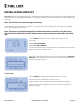
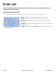
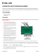
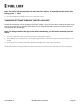
Table Of Contents
- Installation & Operation Manual
- CUSTOMER SUPPORT
- CERTIFICATIONS
- MANUFACTURER’S WARRANTY
- LIABILITY CLAUSES
- 1. The client is defined in the agreement as “the Purchaser”
- 2. IIntraGrain and its authorized distributors are defined in the agreement as “the Seller”
- 3. The item being sold by the Seller is defined in the agreement as “the Product”
- 1. INSTALLATION OF PRODUCT
- 2. EXCLUSION OF LIABILITY
- 3. LIMITATION OF LIABILITY
- 4. RELEASE AND INDEMNITY
- SAFETY
- Standards
- SAFETY INFORMATION
- 1. Turn off electrical power before opening the enclosure cover
- 2. When closing the cover ensure wires are not pinched
- 3. The enclosure box must be electrically grounded
- 4. Do not apply power to the device until instructed to do so
- 5. Perform any line and load voltage wiring in accordance with local and federal authorities and in compliance with the Canadian Electrical Code and National Building Code
- 6. Make sure operator voltage, phase, and frequency nameplate ratings are identical to the job site line voltage ratings
- 7. Input wiring must be properly sized for the operator’s required amperage and must not exceed the nameplate ratings
- 8. Use a padlock on the device to reduce the risk of injury or tampering of the unit
- 9. The unit must not exceed 30 amps and 1hp pump motor rating
- ABOUT FUEL LOCK
- SPECIFICATIONS
- FUEL LOCK INSTALLATION
- COMPONENTS
- TOOLS REQUIRED
- INSTALLATION PROCEDURE
- 1. Identify a suitable mounting location for the Fuel Lock device within the parameters outlined above
- 2. Mount the Fuel Lock device to a stable surface using the 4 screw holes on the outside flanges (a)
- Connecting Fuel Lock To 120v Pumps
- 1. Shut off power to the device
- 2. Connect the line side hot conductor (black, from breaker) to the terminal marked “120V” on the right side of the terminal strip
- 3. Connect the line side neutral conductor (white, from breaker) to one of the three terminals marked “NEUT”
- 4. Connect the load side hot conductor (black) for the fuel pump(s) to the terminal marked either “1” or “2” on the bottom and “120V” on the top.
- 5. Connect the load side neutral conductor (white) for the fuel pump(s) to one of the remaining terminals marked “NEUT”
- 6. Connect the load and line side ground conductors (green or bare) to the ground bar in the bottom left corner of the Fuel Lockenclosure
- 7. Connect the load side hot conductor (black) for the first fuel pump(s) to the terminal marked “1” on the bottom and “120V” on the top
- 8. Connect the load side hot conductor (black) for the second fuel pump(s) to the terminal marked “2” on the bottom and “120V” on the top
- 9. Connect the load side neutral conductor (white) for the second fuel pump(s) to the last remaining terminal marked “NEUT”
- 10. Connect the load and line side ground conductors (green or bare) to the ground bar in the bottom left corner of the Fuel Lock enclosure]
- 11. Install the app to add flow meters
- CONNECTING FUEL LOCK TO 240V PUMPS
- 1. Shut off power to the device
- 2. Connect the second line side hot conductor (from breaker) to the terminal marked “240V” on the right side of the terminal strip
- 3. Connect the second load side hot conductor for the fuel pump(s) to the terminal marked either “1” or “2” on the bottom and “240V” on the top
- 4. Connect the second line side hot conductor (from breaker) to the terminal marked “240V” on the right side of the terminal strip
- 5. Connect the second load side hot conductor for the first fuel pump(s) to the terminal marked “1” on the bottom and “240V” on the top
- 6. Connect the second load side hot conductor for the second fuel pump(s) to the terminal marked “2” on the bottom and “240V” on the top
- FLOW METER - Fuel Lock Business
- INSTALLATION FLOW TEST
- 1. Press *Menu and enter the administrator PIN to gain access
- 2. Press #
- 3. Select #5 Install Support
- 4. Select #1 Tank Calibration
- 5. Ensure the selected port has a pulser that is physically connected to the pulser circuit board inside the device
- 1. Press 0=PWR to engage power supply and turn on pumps
- 2. Ensure the screen is displaying a volume count
- 3. Repeat steps 1 and 2 on all ports with connected tanks (pulsers)
- 4. When volume data is displaying correctly for all tanks, connect the device to the app.
- Setting a Custom Pulse Rate
- a. Ones - toggle (1,4) on the keypad to change the one value.
- b. Tenths - toggle (4,6) on the keypad to change the tenth value.
- c. Hundredths - toggle (7,9) on the keypad to change the hundredths value.
- d. Multiplier - (8) keep the setting at 0L unless instructed by the dealer or IntraGrain support.
- e. Polarity - (5) keep the setting at HIGH unless instructed by the dealer or IntraGrain support.
- FLOW METER CIRCUIT BOARD REPLACEMENT
- TOOLS REQUIRED
- PROCEDURE
- 1. Label the wires connecting the flow meters to the flow meter circuit board and from the customer peripherals side to the circuit board for easier identification when reconnecting to the new circuit board
- 2. Use the small flat screwdriver to loosen the screw terminals on the bottom side of the flow meter board
- 3. Loosen the screw terminals (a) that connect the six wires at the top of the flow meter board, then disconnect the wires
- 4. Loosen the screw terminals (b) that connect the peripheral equipment wires at the bottom of the flow meter board, then disconnect the wires
- 5. Remove the four Phillips screws (c) that secure the flow meter board in place and remove the existing flow meter circuit board from the enclosure
- 6. Place the new flow meter circuit board into the enclosure and secure it with the four Phillips screws (c)
- 7. Reconnect the flow meter wires to the screw terminals (a) at the top of the flow meter board using the labels placed in the first step. The wires must be connected to the terminals in the following order from left to right:
- 8. Reconnect the peripheral equipment wires to the screw terminals (b) at the bottom of the flow meter board using the labels placed in the first step.
- 9. Restore power to the Fuel Lock device
- 10. Unlock the device and pump fuel to test that all connections have been restored and that the new flow meter circuit board is functioning correctly
- USING FUEL LOCK
- AFTER Fuel Lock® IS CONNECTED
- CHANGING YOUR PIN
- 1. From the main lock screen, press * to access the administration page
- 2. Enter your PIN followed by # to gain access to the administration menu (once accepted, the indicator light will blink amber)
- 3. In the administration menu, press 1 to change your PIN
- 4. Follow the on-screen prompts to enter your new PIN (you will be prompted twice)
- 5. Once accepted, you will be returned to the administration menu
- 6. Press * to exit and return to the main lock screen
- USING FUEL LOCK
- CHANGING THE AUTO-LOCK TIME
- 1. From the main lock screen, press * to access the administration page
- 2. Enter your PIN followed by # to gain access to the administration menu (once accepted, the indicator light will blink amber)
- 3. In the administration menu, press 2 to change the auto-lock time
- 4. Enter any time between 5-60 minutes and press # to accept
- 5. Once accepted, you will be returned to the administration menu.
- 6. Press * to exit and return to the main lock screen
- CHANGING THE SCREEN CONTRAST
- 1. From the main lock screen, press * to access the administration page
- 2. Enter your PIN followed by # to gain access to the administration menu (once accepted, the indicator light will blink amber)
- 3. In the administration menu, press 3 to change the screen contrast
- 4. Press 1 to lighten, press 3 to darken
- 5. Once the desired contrast level is reached, press * to save and return to the administration menu
- 6. Press * to exit and return to the main lock screen
- RESTORING DEFAULT SETTINGS
- 1. From the main lock screen, press * to access the administration page
- 2. Enter your PIN followed by # to gain access to the administration menu (once accepted, the indicator light will blink amber)
- 3. In the administration menu, press 4 to restore all settings to their defaults
- 4. Key in the random PIN shown on the screen to erase all current settings (this may take a few minutes)
- 5. Once completed, the device will automatically return to the main lock screen
- CHANGING UNITS AND TIME FORMAT
- 1. From the main lock screen, press * to access the administration page
- 2. Enter your PIN followed by # to gain access to the administration menu. Once accepted, the indicator light will blink amber.
- 3. In the administration menu, press 5 to change units
- 4. Follow the on-screen instruction to change the temperature units and/or time format
- 5. Press # to save and return to the administration menu
- 6. Press * to exit and return to the main lock screen
- Fuel Lock Business
- ERROR MESSAGES
- TROUBLESHOOTING
- MAINTENANCE

www.fuellock.ca November 2021 Version 3.0 Page 24
FLOW METER CIRCUIT BOARD REPLACEMENT
The flow meter circuit board is a small circuit board with electrical connection terminals connecting pulse flow
meters to the Fuel Lock® device. The circuit board is located next to the large terminal strip in the main area of
the Fuel Lock enclosure. The following instructions describe the process for replacing the flow meter circuit board
in the Fuel Lock device.
TOOLS REQUIRED
• Phillips screwdriver
• Small flat screwdriver
• Labeling tape
PROCEDURE
Warning: All power must be disconnected before proceeding. Shut off power to the Fuel Lock device at
the circuit breaker.
1. Label the wires connecting the flow
meters to the flow meter circuit board
and from the customer peripherals side
to the circuit board for easier identifica-
tion when reconnecting to the new cir-
cuit board
2. Use the small flat screwdriver to loosen
the screw terminals on the bottom side
of the flow meter board
3. Loosen the screw terminals (a) that con-
nect the six wires at the top of the flow
meter board, then disconnect the wires
4. Loosen the screw terminals (b) that con-
nect the peripheral equipment wires at
the bottom of the flow meter board, then
disconnect the wires
5. Remove the four Phillips screws (c) that
secure the flow meter board in place
and remove the existing flow meter cir-
cuit board from the enclosure
6. Place the new flow meter circuit board into the enclosure and secure it with the four Phillips screws (c)
7. Reconnect the flow meter wires to the screw terminals (a) at the top of the flow meter board using the labels
placed in the first step. The wires must be connected to the terminals in the following order from left to right:
Red - Black - No connection - White - Brown - Teal - Blue
8. Reconnect the peripheral equipment wires to the screw terminals (b) at the bottom of the flow meter board
using the labels placed in the first step.
9. Restore power to the Fuel Lock device