
User's Manual
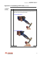
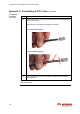
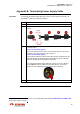
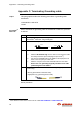
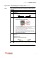
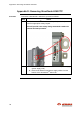
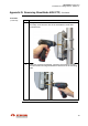
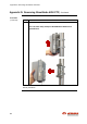
Table Of Contents
- Revisions
- Reasons of change
- Introduction
- Regulations
- General installation guidelines
- (RF exposure)
- Compliance boundary definition
- Table of Contents
- 1. Introduction
- Scope of document
- Target Audience
- Reference manuals
- Conventions
- 2. Prior to Installation
- Topics
- Packing list materials
- Powering materials
- Power injectors
- Power cables
- Power modules & connectors
- Grounding materials
- Data traffic materials
- S-FTP cables
- Fiber optic cables
- SFP
- Pole fastening materials
- Mounting bracket
- Steel hose clamps
- Cable ties
- StreetNodeTM 6250 PTP(1)
- Outdoor DC PonE
- Outdoor AC PonE
- Indoor AC PoE
- Anchor point
- / /
- Introduction
- Site survey
- Preparation of the installation premises
- Network port distributors
- Cables routing (lamp post)
- Power cable routing
- Cable conduits
- Wall installation
- Installation location
- Lamp post or pole
- Grounding
- Outdoor grounding system
- Power supply source
- Circuit breakers
- Line Of Sight (LOS) verification
- Lightning & Surge protection
- Internal ovp(2)
- Safety
- Introduction
- Cable length restrictions
- Instruction
- Topics
- Equipment installation tools
- Ethernet cable termination tools
- Power supply cable termination tools
- Grounding cable termination tools
- 3. Installation of StreetNode 6250 PTP
- Mechanical Installation & Grounding
- Installation of Traffic Cable(s)
- Installation of Power Cable (Direct Powering)
- Installation of Power Injector (Power over Ethernet)
- Appendix A: Terminating Ethernet (S-FTP) Cable
- Appendix B: Terminating Power Supply Cable
- Appendix C: Terminating Grounding cable
- Appendix D: Removing StreetNode 6250 PTP
- Appendix E: Standards of Compliance
- Precautions
- Topics
- Tools and materials
- Lamp post (or pole) installation procedure
- Grounding cable installation procedure
- Topics
- Tools and materials
- Ethernet (S-FTP) cable installation procedure
- Ethernet (S-FTP) cable installation with SFP
- Ethernet (S-FTP) cable installation with SFP
- Topics
- Tools and materials
- Procedure
- Introduction
- Topics
- Tools and materials
- Mechanical and cabling installation (PonE)
- Cabling installation (PoE)
- Introduction
- Parts of RG-45 jack
- Termination procedure
- Procedure
- Topics
- Procedure

StreetNode™ 6250 PTP
Installation & Cabling Manual - Edition 2.1
75
Appendix B: Terminating Power Supply Cable
Procedure
To terminate the power supply cable (AC or DC ) to the respective connector
(1)
of
StreetNode
TM
6250 PTP, proceed as follows:
Step Action
1 Strip approx. 10 mm from the cable’s outer sheath.
2
Pass the connector parts a, b and c over the cable’s end, as shown
below:
3
Strip approx. 4 mm from each wire insulation and solder to the pins of
connector part d.
For the DC connector (2-pin):
There is no polarity concern. Each one of the two wires (1 or 2) can be
soldered to any of the two pins of the connector.
For the AC connector (3-pin):
The AC Mains Earth (E) Yellow / Green wire must be soldered to the pin
shown below with an arrow (the photo shows the connector underside
and more specifically the StreetNode-facing side).
The remaining two black wires marked (1) and (2) are for Live (L) and
Neutral (N) and must be soldered to the other two pins. There is no
polarity concern regarding these two specific wires (1 and 2).
4 Assemble the connector by tightening all parts together.
End of procedure.
(1)
The above procedure is based on the use of cables with order codes AC-PWR-CAB & DC-PWR-CAB-
1 (see Power cables on page 7
)