
Operation Manual


315
PO
SAVE THESE INSTRUCTIONS
English
(315PO) PRISM FRAME
TM
POOL ENGLISH 7.5” X 10.3” PANTONE 295U 06/28/2016
Page 12
POOL SETUP (continued)
YoumayhavepurchasedthispoolwiththeIntexKrystalClear™filterpump.Thepumphasitsown
separate set of installation instructions. First assemble your pool unit and then set up the filter pump.
Estimatedassemblytime30-60minutes.(Notetheassemblytimeisonlyapproximateandindividual
assemblyexperiencemayvary.)
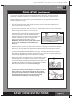
1. Liner preparation
• Findaflat,levellocationthatisfreeandclearofstones,branchesorothersharpobjectsthatmay
puncture the pool liner or cause injury.
• Openthecartoncontainingtheliner,joints,legs,etc.,verycarefullyasthiscartoncanbeusedtostore
the pool during the winter months or when not in use.
• Takeoutthegroundcloth
(10)
(optional)andspreaditover
the cleared area. Then take out the liner
(7)
and spread it
out over the ground cloth, with the drain valve directed
towards the draining area. Place the drain valve away from
the house. Allow the sun to warm up the liner before
inserting the beams
(6)
into the sleeve openings.
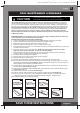
IMPORTANT: Always set up the pool unit with at least 2
persons. Do not drag the liner across the ground as
this can cause liner damage and pool leakage (see
drawing 1).
• Duringthesetupofthispoolliner,pointthehoseconnectionsoropeningsinthedirectionoftheelectric
powersource.Theouteredgeofthepoolshouldbewithinreachofthepump’selectricalconnection.
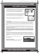
2. Frame assembly
• Theframepool’slegs
(8)
and beams
(6)
fallintotwogroups.Thelargerdiametersarethehorizontal
beamsthatareslid(pushed)intothesleeveopeningsatthetopoftheliner.Thesmallerdiametersare
the vertical legs. Both these legs and beams fit into the T-joints
(3)
.
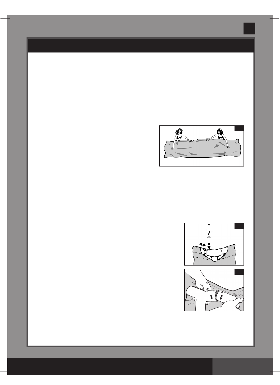
• Startingatanylocation,butalwaysworkinginthesamedirection,push
thehorizontalbeamintothesleeve.Oncethebeamiscenteredtake
one of the T- joints and using the connection pin
(1)
, attach the joint to
one end of the beam by inserting the pin through the seal
(2)
and in the
pre-drilled holes. Repeat this procedure in a circular fashion until all the
beams and joints have been connected
(see drawing 2.1)
.
The last joint connection may be difficult to complete. You can do
it though, if you first simultaneously raisethe last joint and beam
about 2 inches (5 cm). Now insert the beam into the joint while
lowering the pieces into position. The beam will easily slide into
the joint (see drawing 2.2). Ensure that the last joint is fully
connected before proceeding to connecting the legs.
1
7
1
2
6
3
2.1
2.2
3