
Manual


118
PO
SAVE THESE INSTRUCTIONS
(118PO) ULTRA FRAME POOL ENGLISH 7.5” X 10.3” PANTONE 295U 06/20/2013
English
Page 6
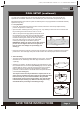
POOL SETUP (continued)
YoumayhavepurchasedthispoolwiththeIntexKrystalClear™filterpump.Thepumphasitsown
separate set of installation instructions. First assemble your pool unit and then set up the filter pump.
Estimatedassemblytime45-60min.(Notetheassemblytimeisonlyapproximateandindividualassembly
experiencemayvary.)
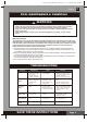
1. Liner preparation
• Findaflat,levellocationthatisfreeandclearofstones,branchesorothersharpobjectsthatmay
puncture the pool liner or cause injury.
• Openthecartoncontainingtheliner,joints,legs,etc.,verycarefullyasthiscartoncanbeusedtostore
the pool during the winter months or when not in use.
• Takeoutthegroundcloth(7) (optional)andspreaditover
the cleared area. Then, take out the liner (5) and spread it
out over the ground cloth, with the drain valve directed
towards the draining area. Place the drain valve away from
the house. Allow the sun to warm up the liner before
inserting the beams (4) into the sleeve openings.
IMPORTANT: Always set up the pool unit with at least 2
persons. Do not drag the liner across the ground as
thiscancauselinerdamageandpoolleakage(see
drawing 1).
• Duringthesetupofthispoolliner,pointthehoseconnectionsoropeningsinthedirectionoftheelectric
powersource.Theouteredgeofthepoolshouldbewithinreachofthepump’selectricalconnection.
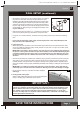
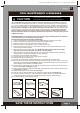
2. Frame assembly
• Theframepool’slegs(2) and beams (4) fall into two groups. The smaller
diameters are the vertical legs. Both these legs and beams fit into the
T-joints (1).
• Startingatanylocation,butalwaysworkinginthesamedirection,push
thehorizontalbeamintothesleeve(see drawing 2.1). Once the beam is
centered take one of the T- joints (1), snap the joint to one end of the
beam by aligning the hole and the spring-loaded pin. Repeat this
procedure in a circular fashion until all the beams and joints have been
connected (see drawing 2.2).
The last joint connection may be difficult to complete, but can be
easily done by simultaneously raising this last joint and beam more
than 2 inches (5 cm), and connect the beam to the joint while
lowering these pieces to their normal position. The joint will slide
intothebeam(seedrawing2.3).Makesurethelastjointisfully
assembled before proceeding to assembling the legs.
1
5
2.1
2.3
1
2.2