
Installation Guide


RS70 Providence Rail System Installation Instructions
RS70INST-1 (05/06/2019)
Special Applications/Situations.
Note: the following situations are not CCRR compliant.
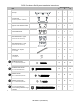
Rail to Newel connections at an angle
This method can be used for angled rail connections to newels, up to a 45 degree angle.
• Determine length and angles for connections to newels at both ends. Cut PVC common rails to
fit, remembering orientation of common rail before cutting (one up, one down). Insure that the
centerline of the rail is aligned with the center of the newel cover.
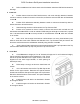
• Measure the short side(s) of the
reinforcement slot in the common rail and
cut the aluminum reinforcement at a 90
degree angle, 3/8” shorter.
• Attach standard level-rail mounting
brackets to the reinforcement. (see Section
3b in main instructions)
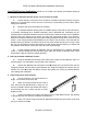
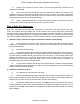
A filler block must be used in the open
triangular space between the bracket and the
newel face. Lay the reinforcement w/bracket
attached into the common rail and determine
size/angle required. Rip a spare baluster to 3/4”
thickness, and cut to fit.
• Attach spacer to newel face using stainless
steel screws and PVC glue. (Place screws at the lower portion of the spacer, to avoid the screws
that will attach the bracket to the newel, which will go through the upper portion.)
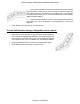
• Position and attach reinforcements to newels as in Sections 4a and 4d in the main instructions.
Insure that attachment screws penetrate into structural newel.
• This method is also used for radius rail attachment to newels, but using the radius rail brackets.
Level Rail Direction Change, 45 degree or 90 degree, not at a Newel.