
Installation Guide
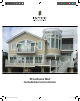


RS70 Providence Rail System Installation Instructions
RS70INST-1 (05/06/2019)
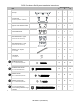
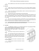
3. Prepare aluminum reinforcements.
a. Attach a Lower Stair Bracket
(90-degree bend) using two rail bracket
screw 🅐 to the lower end of each
reinforcement. Lubricate the threads with
soap to avoid binding and use a clutch type
drill to avoid stripping screws. Note: Do not
cut this end of the reinforcement to the rake
angle.
b. Measure and cut the upper end
of both reinforcements to the rail angle
determined in Step 1, include the protruding portion of the lower bracket as part of the total length.
Attach an upper stair bracket to the angle cut end of the top
rail reinforcement, with the bracket flush with the top of the
reinforcement, using four rail bracket screw 🅐. Attach an
upper stair bracket to the angle cut end of the bottom rail
reinforcement, with the bracket flush with the bottom of the
reinforcement, using four rail bracket screw 🅐. Lubricate the
threads with soap to avoid binding and use a clutch type drill
to avoid stripping screws.
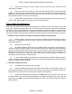
c. Cut one end of Crush Block to angle of rail and
locate to the bottom aluminum rail reinforcement, with
spacing no greater than 32” from the end, or between Crush
Blocks. Ensure that the Crush Block(s) will be located on a stair tread.
d. Drill a 3/16” hole through the Aluminum Rail Reinforcement and secure each Crush Block
using one baluster screw 🅒.
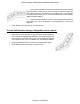
4. Install rail
a. Position bottom aluminum rail reinforcement, with crush block(s) attached, between
newels or columns, centered on newel or column face, and secure each end with two rail attachment
screws 🅑.
b. Position PVC rail/baluster assembly between newels or columns and seat fully down on
bottom aluminum rail reinforcement.
c. Seat remaining aluminum reinforcement into Top Common Rail.
d. Ensure rail is centered on face of newel or column and secure each end with two 4” rail
attachment screws 🅔.
e. Drill a 3/16” hole through the aluminum reinforcement over every third baluster (note:
offset to avoid the screw which is into the top of each baluster) and secure the aluminum
reinforcement to the rail/baluster assembly using baluster screw 🅒
f. Measure and cut Top Cap to required angle and length. Apply a bead of latex caulk at the
contact areas where the Rail Top Cap seats on the Top Common Rail. Seat the Rail Cap fully onto
the Top Common Rail.
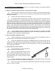
Upper Stair
Bracket
Bottom Rail Reinforcement
Top Rail Reinforcement
Lower Stair Bracket
Upper Stair Bracket