Installation Instructions For Low Profile Mortise Lock A7454A
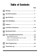
Table of Contents Page 1 Warning .......................................................1 2 General Description .........................................2 3 Specifications ................................................2 4 Parts Breakdown............................................3-5 5 Features .......................................................5 6 Installation Instructions...................................6-13 7 Operational Check ..........................................
1 Warning Warning: Changes or modifications to this unit not expressly approved by the party responsible for compliance could void the user's authority to operate the equipment. This device complies with Part 15 of the FCC Rules. Operation is subject to the following two conditions: (1) this device may not cause harmful interference, and (2) this device must accept any interference received, including interference that may cause undesired operation.
2 General Description The SARGENT Keypad Mortise Lock/Prox is designed for areas which require authorized entry. It is a self-contained microprocessor-controlled keypad with non volatile solid-state memory. The keypad will hold a total of 100(LK) / 500(LU, PK, PA) different User Codes. User Codes “01”, “02”, and “03” are utilized for Master Code, Emergency Code, and Supervisory Code, respectively. This product is operated by six (6) “AA” Duracell Alkaline Batteries.
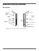
4 Parts Breakdown ’A’ DESIGN (LH) ’A’ DESIGN (RH) ’E’ DESIGN ’B’ DESIGN ’F’ DESIGN ’H’ DESIGN ’J’ DESIGN ’P’ DESIGN ’L’ DESIGN ’W’ DESIGN 12 13 13 26 30 21 17 33 1 24 3 16 22 11 26 8 9 15 24 25 20 23 7 4 31 14 16 5 21 15 17 22 18/19 20 2 11 29 27/28 3
Parts Breakdown (Continued) Item # Part# Description 1 82-3846 82-3847 82-3848 82-3849 82-0493 82-0495 2 82-3837 82-3838 82-3839 82-3840 82-3841 82-3842 82-0492 82-0494 3 4 5 7 8 9 10 11 12 13 14 15 16 17 18 19 20 21 22 23 24 25 26 27 28 29 52-2437 01-1212 01-0297 82-0507 77-0772 01-0844 01-0543 77-0168 52-0033 01-1500 82-3088 01-1495 82-0368 82-0347 82-0081 82-0084 01-1028 01-2299 01-1019 82-0184 01-0079 82-3082 81-0723 01-1472 01-1174 81-0467 81-0468 81-0490 81-0470 81-0471 81-0447 81-0489 81-0513
Parts Breakdown (Continued) Item # 30 31 32 33 Part# Description 82-0151 82-3074 82-0152 82-3073 82-0153 82-0154 82-3074 82-0155 82-3076 82-3079 82-0156 82-0157 82-0158 82-0159 82-3732 82-3733 01-0803 52-0253 O/S Lever Handle R.H. "A" Design O/S Lever Handle R.H. "A" Design Stainless Steel O/S Lever Handle L.H. "A" Design O/S Lever Handle L.H.
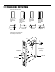
6 Installation Instructions • Verify hand and bevel of door Right Hand Hinges Right Open Inward. "RH" Left Hand Reverse Bevel Hinges Left. Open Outward "LHRB" Left Hand Hinges Left. Open inward. "LH" Right Hand Reverse Bevel Hinges Right. Open Outward.
Installation Instructions (Continued) Door Preparation Thrubolt hole Hole for ribbon cable from controller to keypad Outside of Door Inside of Door Inside Cylinder Hole Thumb Turn Lever Hole Outside Cylinder Hole Mortised area Lever Handle Hole Lever Handle Hole Thrubolt hole Pre-drilled and /or Tapped Holes 2 places NOTE: Always consult the proper template prior to drilling any holes.
Installation Instructions (Continued) How to Reverse Lock Hand If it is necessary to change hand of locking piece : 1. Turn lockbody to side NOT marked with RED locking piece. Connector 2. Insert blade of common screwdriver into locking piece slot. 3. Push locking piece toward front of lockbody and rotate until RED shows. 4. RED indicates locked (outside) side. 5. Wire harness MUST exit thru non-cylinder side.
Installation Instructions (Continued) Step #1 Installation of Lockbody/Attaching Lockbody Screws • Wires and Connector go into the mortised area and out of the inside cylinder hole Inside of Door MUST feed Connector & Wires thru non-cylinder side.
Installation Instructions (Continued) Step #2 Attaching of Fire Stop Plate NOTE: Fire stop plate is required on all fire rated doors (2) 1/8" Dia holes required CL Of 1 1/2" Dia 7" 8 Slot 11" 2 (2) Self Tapping Screws #8 x 1/2" long for wood & metal doors Outside of Door 10
Installation Instructions (Continued) Step #3 Installation of Outside/Inside Escutcheon & Lever Assembly To secure the adapter and plate assembly to the inside of the door, thread the screws mounting posts of the outside lever assembly. From the outside of the door, feed wires and connector through fire stop plate Keypad/prox connector and cable Mortise lockbody connector and wire Tighten retaining nut by hand.
Installation Instructions (Continued) Step #4 Installation of Inside Lever/Outside Cylinder • Align cylinder • Put the turn lever in the up position • Screw cylinder lockbody unit Type 43 Mortise Cylinder ONLY Inside Lever Key • Inside of Door Outside of Door Set Screw • Slide lever handle onto spindle until fully seated.