User’s Guide EasyCoder® PD41 Printer
Intermec Technologies Corporation Corporate Headquarters 6001 36th Ave.W. Everett, WA 98203 U.S.A. www.intermec.com The information contained herein is proprietary and is provided solely for the purpose of allowing customers to operate and service Intermec-manufactured equipment and is not to be released, reproduced, or used for any other purpose without written permission of Intermec.
Contents Before You Begin. . . . . . . . . . . . . . . . . . . . . . . . . . . . . . . . . vii Safety Information . . . . . . . . . . . . . . . . . . . . . . . . vii Global Services and Support . . . . . . . . . . . . . . . . viii Warranty Information . . . . . . . . . . . . . viii Web Support . . . . . . . . . . . . . . . . . . . . viii Telephone Support . . . . . . . . . . . . . . . viii Who Should Read This Manual . . . . . . . . . . . . . . ix Related Documents . . . . . . . . . . . . . . . . . . . . .
LED indicators and the Print Button . . . . . . . . . . . . . . . . . 21 LED indicators. . . . . . . . . . . . . . . . . . . . . . . . . . . 21 Print Button. . . . . . . . . . . . . . . . . . . . . . . . . . . . . 22 3 Maintaining the Printer . . . . . . . . . . . . . . . . . . . 25 General Maintenance Advice . . . . . . . . . . . . . . . . . . . . . . . 26 Printhead Cleaning. . . . . . . . . . . . . . . . . . . . . . . . . . . . . . . 26 Internal Cleaning . . . . . . . . . . . . . . . . . . . . . . . .
A Technical Data . . . . . . . . . . . . . . . . . . . . . . . . . . . . . .49 Printer Specifications. . . . . . . . . . . . . . . . . . . . . . . . . . . . . .50 B Media Specifications . . . . . . . . . . . . . . . . . . . . . . .53 Media Roll Sizes . . . . . . . . . . . . . . . . . . . . . . . . . . . . . . . . .54 Core . . . . . . . . . . . . . . . . . . . . . . . . . . . . . . . . . . .54 Internal Roll . . . . . . . . . . . . . . . . . . . . . . . . . . . . .54 Ribbon Size . . . . . . . . . . . . .
EasyLAN Ethernet Interface . . . . . . . . . . . . . . . . . . . . . . . . 78 Parallel IEEE 1284 Interface. . . . . . . . . . . . . . . . . . . . . . . . 78 Interface cable . . . . . . . . . . . . . . . . . . . . . . . . . . . 78 E Options . . . . . . . . . . . . . . . . . . . . . . . . . . . . . . . . . . . . . . . 81 EasyLAN Ethernet Interface . . . . . . . . . . . . . . . . . . . . . . . . 82 Parallel IEEE 1284 Interface. . . . . . . . . . . . . . . . . . . . . . . . 82 Cutter Kit. . . . . . . . . . .
Before You Begin Before You Begin This section provides you with safety information, technical support information, and sources for additional product information. Safety Information Your safety is extremely important. Read and follow all warnings and cautions in this document before handling and operating Intermec equipment. You can be seriously injured, and equipment and data can be damaged if you do not follow the safety warnings and cautions.
Before You Begin Global Services and Support Warranty Information To understand the warranty for your Intermec product, visit the Intermec web site at www.intermec.com and click Service & Support. The Intermec Global Sales & Service page appears. From the Service & Support menu, move your pointer over Support, and then click Warranty. Disclaimer of warranties: The sample code included in this document is presented for reference only. The code does not necessarily represent complete, tested programs.
Before You Begin Services Description Schedule Site Surveys or Installations Ordering Products Schedule a site survey, or request a product or system installation. Talk to sales administration, place an order, or check the status of your order. In the USA and Canada call 1-800755-5505 and choose this option 4 5 Outside the U.S.A. and Canada, contact your local Intermec representative. To search for your local representative, from the Intermec web site, click Contact.
Before You Begin The Intermec web site at www.intermec.com contains our documents (as PDF files) that you can download for free. To download documents 1 Visit the Intermec web site at www.intermec.com. 2 Click Service & Support > Manuals. 3 In the Select a Product field, choose the product whose documentation you want to download. To order printed versions of the Intermec manuals, contact your local Intermec representative or distributor.
1 Getting Started This chapter introduces the EasyCoder PD41, and explains how to get your new printer connected to your system and print a test label.
Chapter 1 — Getting Started Description of EasyCoder PD41 The EasyCoder PD41 printer is a dependable and versatile printer suitable for medium-duty applications in manufacturing, transportation and warehouse environments. It has all-metal chassis and covers, proven printing mechanics and powerful electronics providing sturdiness, performance and reliability. The EasyCoder PD41 can print demanding crisp variable-data labels continuously at 150 millimeters per second (mm/s) or 6 inches per second (ips).
Chapter 1 — Getting Started 2 Check that no visible damage has occured during transportation. Keep the packing material in case you need to move or reship the printer. 3 Check to make sure any options you ordered are included. 4 In addition to the options you may have ordered, the box should contain the following: • Intermec EasyCoder PD41 printer • Power supply adapter with either one power cord for 115V U.S. wall sockets or two different power cords for 230V European and 240V U.K.
Chapter 1 — Getting Started The discharge of electrostatic energy accumulated on the human body, clothing, or other surfaces can damage or destroy the printhead or electronic components used in this printer. Avoid touching the electrical connectors while unpacking and setting up the printer. Product Identification The machine and serial number labels are attached to the printer’s rear plate, and contain information on type, model and serial number as well as AC voltage and frequency.
Chapter 1 — Getting Started Controls and Indicators Front panel: LEDs and Print button. The blue button on the front panel is the Print button, which also functions as a control button in Testmode. The significance of each of the four LEDs surrounding the Print button is described in the table below. A more complete description of the LEDs can be found in Chapter 2. Control LEDs LED name Light Color Symbol Function Power Green Power indicator. Ready/Data Green Printer ready.
Chapter 1 — Getting Started Rear View Intake for external media supply Side door Machine labels EasyCoder PD41: Rear View Connectors Ethernet RJ-45 connector USB port MAC address label Serial RS-232 port Parallel IEEE 1284 port I O Compact Flash slot Power On/Off switch AC power cord socket Rear view: Connection sockets 6 EasyCoder PD41 Printer User’s Guide
Chapter 1 — Getting Started Media Compartment Ink position lever Edge guide Media supply post Ribbon supply shaft Ribbon rewind shaft EasyCoder PD41: Media Compartment Print Mechanism Ribbon rod Label taken sensor Media feed rods Printhead balance boxes Tear bar Thermal printhead Printhead lever EasyCoder PD41: Print Mechanism EasyCoder PD41 Printer User’s Guide 7
Chapter 1 — Getting Started Installing the Printer Plugging in the Printer 1 Make sure the Power Switch is turned off. 2 Connect the power cable to the printer. 3 Plug the power cable into your electrical outlet. 3 1 2 Connecting the Printer to your System The EasyCoder PD41 is fitted with a USB Type B connector for the USB interface port and one 9-pin D-style subminiature (DB9) socket for the RS-232 serial interface port.
Chapter 1 — Getting Started Connecting the Printer through the USB interface In order to use the USB connection, you need to install the Intermec InterDriver software on your computer. This can be found on the PrinterCompanion CD along with instructions on how to install it. The USB interface is not suitable for terminal connections and thus not for programming. Connecting the Printer to a Network The printer is set to automatically receive an IP number from the network (DHCP).
Chapter 1 — Getting Started Connecting the Printer through the Parallel Port Use the parallel interface (also referred to as“centronics”), with Intermec LabelShop or the Intermec InterDriver. The parallel port supports Windows plug-n-play and additional status reporting through IEEE 1284 nibble ID mode. Printing a Test Label In order to verify that the printer is fully functional and to obtain its current configuration, you can print a test label.
2 Operating the Printer This chapter explains the basic operation of the printer. You will learn how to load media for different types of operation and familiarize yourself with the printer’s control LEDs and the Print button.
Chapter 2 — Operating the Printer Loading Media The EasyCoder PD41 can print on labels, tickets, tags and continuous stock in various formats. Tear-Off (straight-through) Operation This section describes the case when media is torn off manually against the printer’s tear bar. This method is also known as “straight-through” printing.
Chapter 2 — Operating the Printer Tear-Off, continued 3 4 Lift the label feed guide. Load a media roll onto the media supply hub, pushing it all the way in. 5 6 Lock the position of the media roll with the media edge guide. Guide the media through the rods.
Chapter 2 — Operating the Printer Tear-Off, continued 7 8 Route the media through the print mechanism. If using fan-fold media, load it through the rear intake and route the media the same way as a media roll. 9 10 Reset the label feed guide and the printhead lever. Close the side door. Press the Print button to advance the media.
Chapter 2 — Operating the Printer Peel-Off (Self-Strip) Operation This section describes the case when self-adhesive labels are separated from the liner immediately after printing. The same procedure is followed when installing media for Batch Takeup, with the difference that both label and liner is rewound, and the label-taken sensor is not used. These modes of operation require an optional internal rewinder unit, see Appendix E, “Options.” This is also known as self-strip operation.
Chapter 2 — Operating the Printer Peel-Off, continued 3 4 Route the liner through the print mechanism and back as shown above. Wrap the liner on the liner takeup roll and lock it in place. 5 6 Reset the label feed guide and the printhead lever. Reattach the front cover.
Chapter 2 — Operating the Printer Peel-Off, continued 7 8 Push in the location indicated above Turn the Label-Taken Sensor (LTS) to a to bring out the label-taken sensor. fully horizontal position. 9 10 Close the side door. Press the Print button to feed the media.
Chapter 2 — Operating the Printer Loading Thermal Transfer Ribbon Thermal transfer printing makes it possible to use a wide range of receiving face materials and gives a durable printout that is less vulnerable to fat, chemicals, heat, sunlight etc than direct thermal printing. Make sure to select a ribbon type that matches the type of receiving material and set up the printer accordingly. The EasyCoder PD41 can use transfer ribbon rolls wound with the ink-coated side facing either outward or inward.
Chapter 2 — Operating the Printer Loading Ribbon, continued 3 4a Push the ribbon roll onto the right ribbon hub, and the empty ribbon core on the left hub. In case you are using ink-out ribbon, route the ribbon as shown here. 4b 5 In case you are using ink-in ribbon, route the ribbon as shown in this figure. Move the ink-position lever to the left for ink-out ribbon, and to the right for ink-in ribbon.
Chapter 2 — Operating the Printer Loading Ribbon, continued 6 Reset the printhead lever to its original position. Close the side door.
Chapter 2 — Operating the Printer LED indicators and the Print Button The PD41 printer can be in the following “states”, which indicate its current mode of operation. PD41 Printer States State Power Off Upgrading TestMode Extended TestMode PUP Idle Application running Printing Printing (wait for LTS) Paused Error Explanation Firmware is being upgraded. See Chapter 5 for description. See Chapter 5 for description. Power-UP (starting up) Waiting for label-taken sensor to indicate that label has been taken.
Chapter 2 — Operating the Printer The green Ready/Data indicator will be turned on, off or flash depending on the printer’s current state. The behavior of the green Data/Ready and red Error LEDs is shown in the table below. Ready/Data and Error LED behavior State Ready/Data Error Power Off Upgrading Testmode Extended Testmode PUP Idle Application running Printing Printing (wait for LTS) Paused Error Off Off LEDs turned on one after the other. See Chapter 5 for description.
Chapter 2 — Operating the Printer Print Button function State Power Off Upgrading Testmode Extended Testmode Idle Application running Printing Paused Error Button pressed < 1 s Button pressed > 1 s No action No action See “Running Testmode” in Chapter 5 See “Running Testmode” in Chapter 5 Formfeed/Printfeed Testfeed Defined by application Pause print job Continue print job Cancel print job See Chapter 4, “Troubleshooting” EasyCoder PD41 Printer User’s Guide 23
Chapter 2 — Operating the Printer 24 EasyCoder PD41 Printer User’s Guide
3 Maintaining the Printer This chapter explains basic maintenance of the printer. By following the instructions in this chapter you avoid common problems, and increase the lifetime of your printer.
Chapter 3 — Maintaining the Printer General Maintenance Advice In order to attain optimal productivity and a long life for your EasyCoder PD41, it is recommended that you regularly inspect the printer and its operation environment to ensure the printer is operated correctly. Read the EasyCoder PD41 Safety Instructions for basic operational safety requirements. Keep the printer in a dry area, away from larger electrical motors, welders and similar which might affect printer operation.
Chapter 3 — Maintaining the Printer 4 Use a cleaning card or a soft cotton swab moistened with isopropyl alcohol to dissolve any contamination on the line of heat-emitting dots at the front/bottom of the printhead. 5 Wait 30 seconds and carefully rub off any contamination. Repeat if necessary. Never use any hard or sharp tools to peel away stuck labels or similar,. The printhead is delicate and can easily be damaged.
Chapter 3 — Maintaining the Printer Use a soft cloth, possibly moistened with water or a mild detergent when cleaning the printer externally. Make sure to keep the surface surrounding the printer clean as well. If the printer is used in an environment where the premises are cleaned by a water hose or steam, move the printer to another room or cover it very carefully with a plastic sheet and make sure that the power cord is unplugged.
4 Troubleshooting This chapter helps to diagnose problems that may occur during printer operation and how to resolve them.
Chapter 4 — Troubleshooting Printer Operation Problems The following table lists possible problems that affect the printer’s operation. Printing Operation Problems Problem Solution / Reason The Power control LED is • Check that the power cable is correctly not lit when power is connected to printer and electrical switched on. outlet. Error LED turns solid red • Check if printer is out of media or after printing. ribbon. • Check if media is jammed or tangled.
Chapter 4 — Troubleshooting Print Quality Problems Print Quality Problems Problem Solution / Reason Printout is faded or weak • Check the media settings: Constant, Factor and Contrast. • Check if printhead needs cleaning. • Check printhead pressure. • Check printhead dotline position. Printer is working but • Check if media is placed upside down. nothing is printed • Ensure that the ink-side of the ribbon faces the media. • Select the correct media type, direct thermal or thermal transfer printing.
Chapter 4 — Troubleshooting Ready-to-Work™ Indicator The blue Ready-to-Work LED is lit when the printer is operational. It can be turned off or flash in case something is not working as expected. Ready-to-Work LED Flashing or Off The Ready-to-Work indicator is set to flash when the printer is receiving data, as well as under several different error conditions. Normally, this is due to an IP link error, where the printer has a network card but has not yet received an IP number.
Chapter 4 — Troubleshooting Ribbon Shield Adjustment The ribbon shield mechanism is located on the thermal printhead. It has two adjustable screws, A and B, as shown below. A B Ribbon shield adjustment screws If the label printout matches Test label A, turn screw A clockwise. If the printout matches Test label B, turn screw B clockwise. Turn the screw half a circle and perform a new test printing. Continue until you achieve a smooth printout quality.
Chapter 4 — Troubleshooting tools that can damage the platen roller or printhead. Avoid rotating the platen roller. Take care to avoid causing the platen roller to rotate. The electronic components may be damaged permanently. 4 Cut off any damaged or wrinkled part of the media. 5 Check to see if there is any adhesive somewhere in the print mechanism. If so, follow the cleaning instructions in the section “Internal Cleaning” in Chapter 3. 6 Reload the media as described in Chapter 2. 7 Switch on the power.
Chapter 4 — Troubleshooting Balance box 5 Engage the printhead and load the ribbon. 6 Test and readjust if necessary. (Tip: Use direct thermal media to avoid loading and unloading of ribbon multiple times.) Adjusting Printhead Pressure The pressure of the thermal printhead against the platen roller is factory-adjusted.
Chapter 4 — Troubleshooting 5 Engage the printhead and load the ribbon. 6 Test and readjust if necessary. (Tip: Use direct thermal media to avoid loading and unloading of ribbon multiple times.) Adjusting Printhead Dot Line When using thick or stiff media, the printhead needs to be moved forward so the dot line is aligned precisely with the top of the platen roller. They must of course be perfectly parallel as well. 1 Open the side door. 2 Remove the ribbon and engage the printhead.
Chapter 4 — Troubleshooting tighten both screws completely by turning them counterclockwise as far as they go and start over. 6 Engage the printhead and lock the printhead by tightening the two screws at the top of the printhead bracket, that is, the reverse action of step 3. 7 Load the ribbon (if any). 8 Test and readjust if necessary. (Tip: Use direct thermal media to avoid loading and unloading of ribbon multiple times.
Chapter 4 — Troubleshooting Sensor lever 2 Check the point of detection from the front (with the printhead lifted.
5 Setting up the Printer The EasyCoder PD41 has many settings that control printer operation, communication settings, media types and more. This chapter describes the printer’s startup sequence and explains how to set or change setup parameters. It also includes a description of the two Testmodes available, and a guide on firmware upgrading.
Chapter 5 — Setting up the Printer The Printer Startup Sequence When switched on, the printer will go through a sequence of steps in order to decide what settings should be set and what application (if any) should be started. Printer Startup Sequence 1 Check for firmware binary on CompactFlash card. If so, upgrade. Note: If the CompactFlash contains an earlier firmware version than one installed in the printer, the printer’s firmware will be downgraded. 2 Check if printhead is lifted and button is pressed.
Chapter 5 — Setting up the Printer Changing Configuration Settings The complete list of setup options can be found in Appendix C. Depending on the communication method you use with your printer, you can set configuration settings with different methods. Using PrintSet 4 The recommended way to set your printer’s configuration is to use the included PrintSet 4 program. PrintSet 4 can communicate with your printer either via a serial cable or a network connection.
Chapter 5 — Setting up the Printer Running Testmode You can check certain settings, print a test label, or enter the dump mode for troubleshooting purposes by using the printer testmodes. Two testmodes are available, Testmode and Extended Testmode. Testmode Normal testmode is used to select the media type, to print test labels, and to enter dump mode. Testmode is entered by pressing the Print button while switching the printer’s power on.
Chapter 5 — Setting up the Printer Testmode: Printing Test Labels Data/ Step Ready Error 5 RtW Button Comment The printer will then print four test labels after the testfeed in step 4. To skip any test labels tap the button. Testmode: Running the Dump mode Data/ Step Ready Error 6 7 8 RtW Button Comment The printer is now in Dumpmode and the printer scans the communication ports. The printer will print any characters it received on the communication ports to a label when exiting dump mode.
Chapter 5 — Setting up the Printer Extended Testmode: Activating Data/ Step Ready Error RtW 1 2 Button Comment 1 flash flash Make sure the printhead is lifted. Press and hold the Print button and switch the printer On. Extended Testmode is activated after 10 seconds. All 3 LEDs flash rapidly four times. Extended Testmode is activated. Release button to continue.
Chapter 5 — Setting up the Printer Extended Testmode: 7a - Test Label Function Data/ Step Ready Error RtW 7a 1 Button Comment LED flashes once per second. 1 Tap the Print button, once for each of 7test labels. Press Print button and hold it to exit Test Label function and return to Step 6. Extended Testmode: 7b - Testfeed Mode Slow Function Data/ Step Ready Error 7b RtW Button Comment 1 LEDs flash once per second. 1 Tap the Print button to start Testfeed (Mode slow). Test label is printed.
Chapter 5 — Setting up the Printer Extended Testmode: 7d - Factory Default Function Data/ Step Ready Error 7d RtW Button Comment 1 LEDs flash once per second. Lift the printhead, tap the Print button, and lower the printhead. LEDs will flash. Tap the button. Printer will start resetting to factory defaults. This is indicated by scrolling LEDs. 1 LED flashes once per second, indicating factory default reset is done. Press the button > 1 second to perform testfeed.
Chapter 5 — Setting up the Printer Upgrading Firmware The www.intermec.com web site contains the latest software that you can download for free. To download firmware updates 1 Visit the Intermec web site at www.intermec.com. 2 Click Service & Support > Downloads. 3 In the Select a Product field, choose the EasyCoder PD41 and you will be presented with the latest software available. 4 Download the latest firmware version to your computer. 5 Extract the zip file to a folder on your computer.
Chapter 5 — Setting up the Printer 48 EasyCoder PD41 Printer User’s Guide
A Technical Data This Appendix lists technical specifications for the EasyCoder PD41. The appendix contains: • Table of Printer Specifications.
Appendix A — Technical Data Printer Specifications Printer Specifications Table Physical Dimensions Dimensions (WxLxH) 276 x 454.4 x 283.0 mm (10.85 x 17.9 x 11.2 inches) Weight (excl. media) 13 kg (28.7 pounds) Power Supply Input Rating Power Consumption 100-240 VAC, 3-1 A, 50-60 Hz • Stand-by : 12W • Normal operation/printing: 80W • Peak: 250W Printing Print Technique Printhead Resolutions Print Speed 8 dots/mm (203 dpi) 11.8 dots/mm (300dpi) Print Width Max. 8 dots/mm (203 dpi) 11.
Appendix A — Technical Data Printer Specifications Table Resident scaleable fonts 15 Character Sets • 23 single-byte character sets standard. • UTF-8 support as standard.
Appendix A — Technical Data Printer Specifications Table Electronics Micropocessor Standard Memory ARM 9 4 MB Flash, 8 MB SDRAM.
B Media Specifications This appendix illustrates the different media types the EasyCoder PD41 can operate with, and states the allowed dimensions of the paper, ribbon and rolls.
Appendix B — Media Specifications Media Roll Sizes The media roll must comply with the following dimensions: Media roll dimensions Core Diameters: Width: 38 to 76.2 mm (1.5 to 3 inches) Must not protrude outside the media. Internal Roll Max. diamater Max diameter with internal rewinder Max. width Max. width with cutter Min. width Thickness 212 mm 190 mm 8.35 inches 7.5 inches 118 mm 114 mm 25 mm 60 to 250 μm 4.65 inches 4.49 inches 1.00 inches 2.3 to 9.
Appendix B — Media Specifications The media supply must not be exposed to sand, dust, grit etc. Any hard particles, no matter how small, can damage the printhead. Ribbon Size The core of the ribbon must be 25.2-25.6 mm (1 inch), as the empty ribbon core included in the box. The outer dimensions of the ribbon roll may be: Max. diameter Max. width Min. width 76 mm 110 mm 30 mm EasyCoder PD41 Printer User’s Guide 2.99 inches 4.33 inches 1.
Appendix B — Media Specifications Paper Types and Sizes Non-Adhesive Strip a: Media Width Maximum: Minimum: 118.0 mm 25.0 mm 4.65 inches 1.
Appendix B — Media Specifications Self-Adhesive Strip a: Media Width Maximum: Minimum: 118.0 mm 25.0 mm 4.65 inches 1.00 inches b: Liner The liner must extend evenly on both sides and not more than a total of 1.6 mm (0.06) inches outside the face material. c: Media Width (excluding liner) Maximum: Minimum: 116.4 mm 23.8 mm 4.58 inches 0.
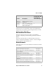
Appendix B — Media Specifications Self-Adhesive Labels a: Media Width Maximum: Minimum: 118.0 mm 25.0 mm 4.65 inches 1.00 inches b: Liner The liner must extend evenly on both sides and not more than a total of 1.6 mm (0.06) inches outside the face material. c: Label Width (excluding liner) Maximum: Minimum: 116.4 mm 23.8 mm 4.58 inches 0.94 inches d: Label Length 8 dots/mm (203 dpi) Maximum: 1270 mm* Minimum: 6 mm 11.81 dots/mm (300 dpi) Maximum: 558.8 mm* Minimum: 6 mm 50 inches 0.
Appendix B — Media Specifications a c d e SELF-ADHESIVE LABELS b b FEED DIRECTION Self-adhesive Labels EasyCoder PD41 Printer User’s Guide 59
Appendix B — Media Specifications Tickets with Gaps a: Media Width Maximum: Minimum: 118.0 mm 25.0 mm 4.65 inches 1.00 inches b: Copy Length 8 dots/mm (203 dpi) Maximum: 1270 mm* Minimum: 6 mm 11.81 dots/mm (300 dpi) Maximum: 558.8 mm* Minimum: 6 mm 50 inches 0.2 inches 22 inches 0.2 inches * This is the print length limit set by memory constraints. c: Detection Position Variable: 0 to 57 mm 0 to 2.
Appendix B — Media Specifications a c b e d TICKETS & TAGS FEED DIRECTION Tickets with Gaps EasyCoder PD41 Printer User’s Guide 61
Appendix B — Media Specifications Tickets with Black Mark a: Media Width Maximum: Minimum: 118.0 mm 25.0 mm 4.65 inches 1.00 inches b: Copy Length 8 dots/mm (203 dpi) Maximum: 1270 mm* Minimum: 6 mm 11.81 dots/mm (300 dpi) Maximum: 558.8 mm* Minimum: 6 mm 50 inches 0.2 inches 22 inches 0.2 inches * This is the print length limit set by memory constraints. c: Detection Position Variable: 0 to 57 mm 0 to 2.24 inches d: Black Mark Width The detectable width of the black mark should be at least 5.
Appendix B — Media Specifications Note: Preprint that may interfere with the detection of the black mark should be avoided. Note: the black mark should be non-reflective carbon black on a white or near-white background. Do not allow any perforations to break the edge of the media as this may cause the media to split and jam the printer.
Appendix B — Media Specifications 64 EasyCoder PD41 Printer User’s Guide
C Setup Parameters This appendix lists all of the setup parameters that you can configure to fit your operating environment.
Appendix C — Setup Parameters Setup Description The printer’s Setup parameters are used to set the printer’s operational behavior. Chapter 5, “Configuring Settings”, explains how to set or change the parameters, and this is also explained in the Fingerprint v10.X.X Programmer’s Reference Manual, under the SETUP command.
Appendix C — Setup Parameters Character Length The character length specifies the number of bits that will define a character. Eight bits are recommended, since that option allows more special characters and characters that are used exclusively in foreign languages. Refer to the Intermec Fingerprint v10.X.X, Programmer’s Reference Manual for more information. • 7 (Characters ASCII 000 to 127 decimal) • 8 (Characters ASCII 000 to 255 decimal). Default.
Appendix C — Setup Parameters XON/XOFF is a protocol in which communication is controlled by the control characters XON (ASCII 17 dec.) and XOFF (ASCII 19 dec.) transmitted on the same line as the data. XON/ XOFF can be enabled/disabled separately for data received from the host by the printer (printer sends XON/XOFF) and for data transmitted to the host from the printer (host sends XON/ XOFF). New Line Selects the character or characters transmitted from the printer to indicate a new line.
Appendix C — Setup Parameters origin is moved further back from the forward edge of the copy. • A negative start adjustment means that the specified length of media will be pulled back before the printing starts. Thus, the origin is moved towards the forward edge of the copy. Stop Adjust The Stop Adjust value is given as a positive or negative number of dots. Default value is 0, which stops the media feed in a position suitable for tear off operation.
Appendix C — Setup Parameters Width Specifies the width of the printable area in number of dots from the origin. Thus, the sum of the X-start and width values gives the outer margin of the printable area. The width should be set to prevent printing outside the media, which may harm the printhead. Length Specifies the length of the printable area in number of dots from the origin along the Y-coordinate and allocates memory space for two identical image buffers in the printer’s temporary memory.
Appendix C — Setup Parameters 14 mm (0.55 in) max. 104.0 mm (4.095 in) Length Dot-line on printhead Origin X-start Dot #0 PRINT WINDOW Width (1-832 dots) FEED DIRECTION Dot #831 25-118 mm (1-4.65 in) Print Window: 8 dots/mm standard printhead Media Type The Media Type parameter controls how the label stop sensor (LSS) and the media feed work. There are five media type options, see also Appendix B, “Media Specifications”: • Label (w gaps) is used for adhesive labels mounted on liner.
Appendix C — Setup Parameters • Error 1031 “Next label not found” indicates that the last ordered label or ticket was successfully printed, but no more labels/tickets can be printed because of an empty media stock. Paper Type The Paper Type parameters control the heat emitted from the printhead to the direct thermal media or, optionally, the transfer ribbon in order to produce the dots that make up the printout image.
Appendix C — Setup Parameters Direct Thermal Recommmended Settings Paper Label sensitivity Constant Low Standard High Ultra High Label Factor Max Print Speed (203 dpi Max Print Speed (300 dpi) 40 40 40 40 75 100 125 150 50 75 100 100 100 90 80 70 Use the above settings as initial settings and adjust the Label Constant if necessary. Thermal Transfer printing • Ribbon Constant (range 50 to 115). Default 90. • Ribbon Factor (range 10 to 50). Default 25. • Label Offset (range -50 to 50). Default 0.
Appendix C — Setup Parameters Contrast Use the contrast parameter to make minor adjustments of the blackness of the printout, for example to adapt the printer to variations in quality between different batches of the same media. The options are values between -10% to 10% in steps of 2. Default value is 0%. The contrast is reset to the default value whenever a new paper type is specified, regardless which method has been used.
D Interfaces This appendix describes the default interfaces, as well as the optional kits that add functionality to your EasyCoder PD41.
Appendix D — Interfaces RS-232 Serial Interface Protocol Default Setup Baud rate Character length Parity Stop bits Handshaking 9600 8 bits None 1 XON/XOFF and RTS/CTS To change the Serial settings, see Chapter 5, “Configuring Setup”. Interface cable The computer end of the cable depends on the computer model. The printer end is a DB-9pin plug, as shown below.
Appendix D — Interfaces USB Interface The printer supports USB v1.1 (also called USB 2.0 full speed). To use the USB interface to print from a PC, you need to have the Intermec USB printer driver installed on your PC. You will find this driver (InterDriver) on the Printer Companion CD along with installation instructions. The printer is a so called “self-powered device”. We recommend that you only connect one printer to each USB port on the host, either directly or via a hub.
Appendix D — Interfaces EasyLAN Ethernet Interface The EasyLAN Ethernet interface has an RJ-45 socket for use with a standard RJ-45 cable. The interface supports 10/100 Mbps Fast Ethernet (10BASE-T, 100BASE-TX) and is fully compliant to the IEEE 802.3u standard. The network card MAC adress can be found on the label below the socket. Network status LEDs Ethernet RJ-45 connector Ethernet RJ-45 socket One yellow and one green LED indicate the network status.
Appendix D — Interfaces Pinout Description Pin Function Transmitter 14 15-16 17 18 19-30 31 32 33 34-35 36 nAutoFd Not connected Chassis ground External +5V DC Signal ground nInit nFault printer Signal ground Not connected nSelectln EasyCoder PD41 Printer User’s Guide Comment Max 500mA 79
Appendix D — Interfaces 80 EasyCoder PD41 Printer User’s Guide
E Options This appendix describes the options that add functionality to your EasyCoder PD41 Printer. For a complete description and installations instructions, see the respective installation instructions document for each kit. Please note that several of these options can only be factory-fitted or installed by an authorized service technician.
Appendix E — Options EasyLAN Ethernet Interface The EasyLAN Ethernet Interface kit adds network capability to your printer. See “Interfaces” in Appendix D. Parallel IEEE 1284 Interface This kit adds a parallel (“centronics”) port to your printer. See the “Interfaces” in Appendix D. Cutter Kit The Cutter is designed to cut off continuous paper-based stock or liner between labels. The paper cutter can be controlled using the instructions CUT, CUT ON and CUT OFF in Fingerprint (and Direct Protocol).
Appendix E — Options EasyCoder PD41 Printer User’s Guide 83
Corporate Headquarters 6001 36th Avenue West Everett, Washington 98203 U.S.A. tel 425.348.2600 fax 425.355.9551 www.intermec.