
Quick Start Guide


ITRF24501 Reader Quick Start Guide
8
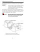
The following illustration is an example of a typical Reader
installation.
EXAMPLE: Two Product Line Conveyers, showing two antennas
on each line. Two antennas in a crossing pattern
provide angular diversity to improve read capability
when tag orientation is unknown.
The frames for these stations are PVC tubing with RF reflec-
tive Mylar liner X2. Ensure that an eight inch (20 c m) distance
from the antenna assembly is maintained to limit people’s ex-
posure to radiofrequency (RF) radiation.
WARNING: While the device is on, the operator’s body and
parts of the body such as eyes, hands, o r head,
must be 20 cm. (8 inches) or farther from the
cover of the antenna assembly.
Conveyer Belt #1
Conveyer Belt #2
33” Max.
distance
to tag
A singular antenna in a portal may be sufficient
in applications where there is a known tag orientation